Plot the graphs of the outputs of the circuits in scale according to the input signal. and provide information about varactor structure and usage areas
Plot the graphs of the outputs of the circuits in scale according to the input signal.
and provide information about varactor structure and usage areas

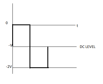
a) The diode is biased to the front and thus no signal appears on the output during the positive half-cycle of the AC input signal. In a biased diode, electric current can be obtained. The current flows to the condenser or capacitor and loads it into reverse polarity, with the peak input voltage (-V).
The diode is reverse biased and therefore signal voltage is displayed at the output during a negative half cycle. The diode is in non-conducting stages when the negative half cycle begins and the charge in the condenser is released. Thus voltage is displayed in all outputs, which is the sum of voltage stored in condenser (-V) and input voltage (-V). The output voltage is therefore -2V. As a consequence, the signal went down.

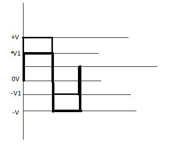
In figure a second circuit is negative clamper with positive bias. With no input signal capacitor charges with battery voltage. Output waveform is clamped to +V1 voltage that is value of battery. Since it is negative clamper top output voltage will touch the reference line of battery voltage.

Step by step
Solved in 2 steps with 3 images


