**Problem 1:** Initially, the switch in Fig. 1 is in its position A and capacitors \(C_2\) and \(C_3\) are uncharged. Then the switch is flipped to position B. Afterward, what are the charge on and the potential difference across each capacitor? **Partial answer:** \(\Delta V_1 = 55 \, \text{V}, \, \Delta V_2 = 33.5 \, \text{V}\). a) While the capacitor is in position A, as shown in Fig. 1, compute the charge \(Q\) accumulated on the plates of the capacitor \(C_1\). **Fig. 1: The scheme for Problem 1** - **Diagram Elements:** - A 100V battery - Capacitor \(C_1 = 15\mu F\) - Capacitor \(C_2 = 20\mu F\) - Capacitor \(C_3 = 30\mu F\) - Switch initially at position A b) After the switch is flipped to position B, the battery is no longer connected to the contour and the charge redistributes between the capacitors as shown in Fig. 2. Notice that the segment between capacitors \(C_2\) and \(C_3\) has to be neutral (therefore, they have the same charge), but the segments connecting \(C_1\) to \(C_2\) and \(C_1\) to \(C_3\) are not neutral. What can you say about the sum of charges \(Q_1\) and \(Q_2\)? **Fig. 2: The scheme for Problem 1b** - **Diagram Elements:** - Capacitors depicted to show redistributed charges - Segment between \(C_2\) and \(C_3\) is charge neutral - Charge \(Q_1\) on \(C_1\), redistributing to \(Q_2\) on \(C_2\) and \(C_3\) c) Use Kirchhoff’s loop law to get another relation between charges \(Q_1\) and \(Q_2\). Starting from point B in Fig. 2, move counterclockwise along the loop and register the potential differences that you encounter when crossing the capac
**Problem 1:** Initially, the switch in Fig. 1 is in its position A and capacitors \(C_2\) and \(C_3\) are uncharged. Then the switch is flipped to position B. Afterward, what are the charge on and the potential difference across each capacitor? **Partial answer:** \(\Delta V_1 = 55 \, \text{V}, \, \Delta V_2 = 33.5 \, \text{V}\). a) While the capacitor is in position A, as shown in Fig. 1, compute the charge \(Q\) accumulated on the plates of the capacitor \(C_1\). **Fig. 1: The scheme for Problem 1** - **Diagram Elements:** - A 100V battery - Capacitor \(C_1 = 15\mu F\) - Capacitor \(C_2 = 20\mu F\) - Capacitor \(C_3 = 30\mu F\) - Switch initially at position A b) After the switch is flipped to position B, the battery is no longer connected to the contour and the charge redistributes between the capacitors as shown in Fig. 2. Notice that the segment between capacitors \(C_2\) and \(C_3\) has to be neutral (therefore, they have the same charge), but the segments connecting \(C_1\) to \(C_2\) and \(C_1\) to \(C_3\) are not neutral. What can you say about the sum of charges \(Q_1\) and \(Q_2\)? **Fig. 2: The scheme for Problem 1b** - **Diagram Elements:** - Capacitors depicted to show redistributed charges - Segment between \(C_2\) and \(C_3\) is charge neutral - Charge \(Q_1\) on \(C_1\), redistributing to \(Q_2\) on \(C_2\) and \(C_3\) c) Use Kirchhoff’s loop law to get another relation between charges \(Q_1\) and \(Q_2\). Starting from point B in Fig. 2, move counterclockwise along the loop and register the potential differences that you encounter when crossing the capac

Introductory Circuit Analysis (13th Edition)
13th Edition
ISBN:9780133923605
Author:Robert L. Boylestad
Publisher:Robert L. Boylestad
Chapter1: Introduction
Section: Chapter Questions
Problem 1P: Visit your local library (at school or home) and describe the extent to which it provides literature...

Related questions
Question
Hello, I only need help with part B because I don't understand it. thank you.

Transcribed Image Text:**Problem 1:**
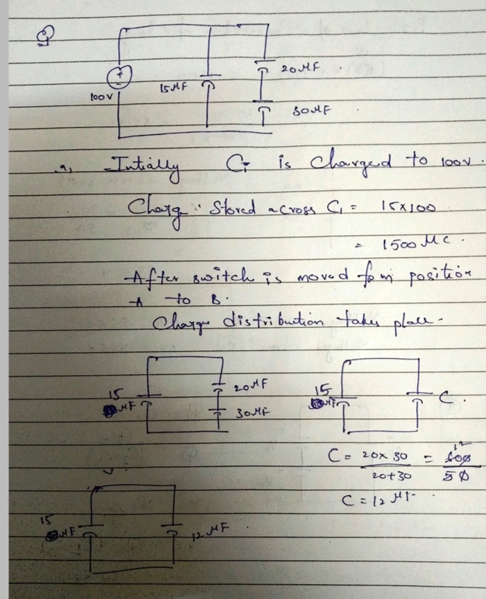
Initially, the switch in Fig. 1 is in its position A and capacitors \(C_2\) and \(C_3\) are uncharged. Then the switch is flipped to position B. Afterward, what are the charge on and the potential difference across each capacitor?
**Partial answer:** \(\Delta V_1 = 55 \, \text{V}, \, \Delta V_2 = 33.5 \, \text{V}\).
a) While the capacitor is in position A, as shown in Fig. 1, compute the charge \(Q\) accumulated on the plates of the capacitor \(C_1\).
**Fig. 1: The scheme for Problem 1**
- **Diagram Elements:**
- A 100V battery
- Capacitor \(C_1 = 15\mu F\)
- Capacitor \(C_2 = 20\mu F\)
- Capacitor \(C_3 = 30\mu F\)
- Switch initially at position A
b) After the switch is flipped to position B, the battery is no longer connected to the contour and the charge redistributes between the capacitors as shown in Fig. 2. Notice that the segment between capacitors \(C_2\) and \(C_3\) has to be neutral (therefore, they have the same charge), but the segments connecting \(C_1\) to \(C_2\) and \(C_1\) to \(C_3\) are not neutral. What can you say about the sum of charges \(Q_1\) and \(Q_2\)?
**Fig. 2: The scheme for Problem 1b**
- **Diagram Elements:**
- Capacitors depicted to show redistributed charges
- Segment between \(C_2\) and \(C_3\) is charge neutral
- Charge \(Q_1\) on \(C_1\), redistributing to \(Q_2\) on \(C_2\) and \(C_3\)
c) Use Kirchhoff’s loop law to get another relation between charges \(Q_1\) and \(Q_2\). Starting from point B in Fig. 2, move counterclockwise along the loop and register the potential differences that you encounter when crossing the capac
Expert Solution
Step 1

Step by step
Solved in 3 steps with 3 images

Knowledge Booster


Learn more about
Need a deep-dive on the concept behind this application? Look no further. Learn more about this topic, electrical-engineering and related others by exploring similar questions and additional content below.Recommended textbooks for you
Introductory Circuit Analysis (13th Edition)
Electrical Engineering
ISBN:
9780133923605
Author:
Robert L. Boylestad
Publisher:
PEARSON

Delmar's Standard Textbook Of Electricity
Electrical Engineering
ISBN:
9781337900348
Author:
Stephen L. Herman
Publisher:
Cengage Learning

Programmable Logic Controllers
Electrical Engineering
ISBN:
9780073373843
Author:
Frank D. Petruzella
Publisher:
McGraw-Hill Education
Introductory Circuit Analysis (13th Edition)
Electrical Engineering
ISBN:
9780133923605
Author:
Robert L. Boylestad
Publisher:
PEARSON
Delmar's Standard Textbook Of Electricity
Electrical Engineering
ISBN:
9781337900348
Author:
Stephen L. Herman
Publisher:
Cengage Learning
Programmable Logic Controllers
Electrical Engineering
ISBN:
9780073373843
Author:
Frank D. Petruzella
Publisher:
McGraw-Hill Education

Fundamentals of Electric Circuits
Electrical Engineering
ISBN:
9780078028229
Author:
Charles K Alexander, Matthew Sadiku
Publisher:
McGraw-Hill Education

Electric Circuits. (11th Edition)
Electrical Engineering
ISBN:
9780134746968
Author:
James W. Nilsson, Susan Riedel
Publisher:
PEARSON

Engineering Electromagnetics
Electrical Engineering
ISBN:
9780078028151
Author:
Hayt, William H. (william Hart), Jr, BUCK, John A.
Publisher:
Mcgraw-hill Education,