Perp, サ+ しexルっ) DETERMINE THE INTEENAL FURCES ROR MEMBERO AC @ 4 ONLT FOR THE Teuss SHolwn ABOVE BY THE METHOD oF sECTA Page 1 1
Perp, サ+ しexルっ) DETERMINE THE INTEENAL FURCES ROR MEMBERO AC @ 4 ONLT FOR THE Teuss SHolwn ABOVE BY THE METHOD oF sECTA Page 1 1
Chapter2: Loads On Structures
Section: Chapter Questions
Problem 1P
Related questions
Question
100%

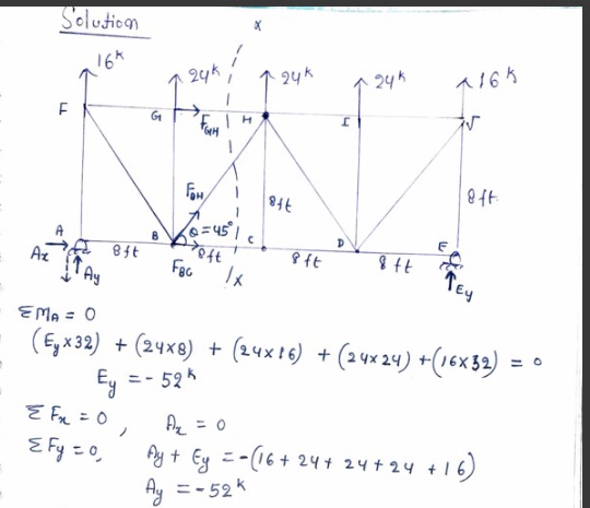
Transcribed Image Text:### Problem Statement
**Structure Details:**
- A truss structure is shown with joints labeled from A to E and load applications at points G, H, and J.
- Vertical supports are shown at points A and E.
- The horizontal segments between joints are all 8 feet apart.
**Loads:**
- At point G: 10 kips
- At point H: 24 kips
- At point J: 24 kips
- At the end of the truss: 10 kips at joint J
**Supports:**
- A pinned support at joint A, allowing rotation but no horizontal movement, indicated by the triangular symbol.
- A roller support at joint E, allowing horizontal movement but not vertical movement, depicted by a circle with an underlying line.
### Task
**Objective:**
Determine the internal forces for members BC and GH only, using the **method of sections**.
**Instructions:**
Analyze the forces acting on the specified truss members using statics principles and the method of sections, focusing specifically on BC and GH. Consider the equilibrium of forces acting on sections of the truss to find the internal forces.
Expert Solution
Step 1

Step by step
Solved in 2 steps with 2 images

Recommended textbooks for you


Structural Analysis (10th Edition)
Civil Engineering
ISBN:
9780134610672
Author:
Russell C. Hibbeler
Publisher:
PEARSON

Principles of Foundation Engineering (MindTap Cou…
Civil Engineering
ISBN:
9781337705028
Author:
Braja M. Das, Nagaratnam Sivakugan
Publisher:
Cengage Learning


Structural Analysis (10th Edition)
Civil Engineering
ISBN:
9780134610672
Author:
Russell C. Hibbeler
Publisher:
PEARSON

Principles of Foundation Engineering (MindTap Cou…
Civil Engineering
ISBN:
9781337705028
Author:
Braja M. Das, Nagaratnam Sivakugan
Publisher:
Cengage Learning

Fundamentals of Structural Analysis
Civil Engineering
ISBN:
9780073398006
Author:
Kenneth M. Leet Emeritus, Chia-Ming Uang, Joel Lanning
Publisher:
McGraw-Hill Education


Traffic and Highway Engineering
Civil Engineering
ISBN:
9781305156241
Author:
Garber, Nicholas J.
Publisher:
Cengage Learning