On the part attached, what is the flatness on the top surface with only the profile applied? And apply a 0.1 flatness control to the top surface.
On the part attached, what is the flatness on the top surface with only the profile applied? And apply a 0.1 flatness control to the top surface.

Elements Of Electromagnetics
7th Edition
ISBN:9780190698614
Author:Sadiku, Matthew N. O.
Publisher:Sadiku, Matthew N. O.
ChapterMA: Math Assessment
Section: Chapter Questions
Problem 1.1MA

Related questions
Question
On the part attached, what is the flatness on the top surface with only the profile applied? And apply a 0.1 flatness control to the top surface.

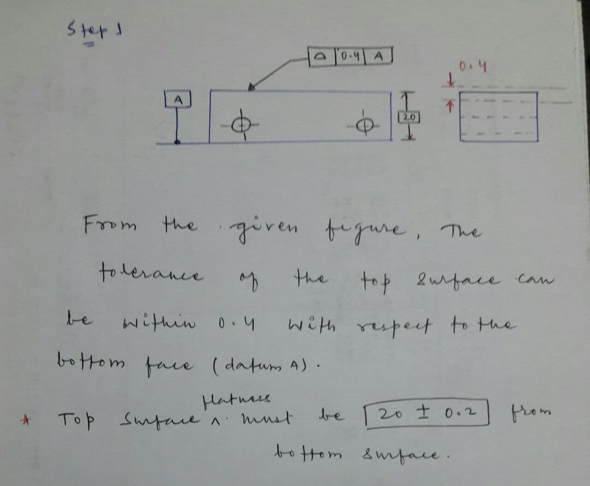
Transcribed Image Text:The image depicts a mechanical engineering drawing with geometric dimensioning and tolerancing (GD&T) annotations.
### Explanation of Key Components:
1. **Rectangular Object**:
- The main feature in the diagram is a shaded rectangular block, which appears to have two holes or circular features. These are indicated by center marks (+) on the rectangle.
2. **Datum Feature**:
- The rectangle is associated with a datum symbol labeled "A" on the left side. This indicates that the surface next to this symbol is considered as the primary datum reference for this drawing.
3. **Hole Annotation**:
- There is a callout pointing to the circle features on the rectangle, which includes a geometric tolerance feature control frame.
- The frame contains a semicircle symbol followed by "0.4" and "A". The semicircle likely indicates a profile of a surface tolerance, with a tolerance of 0.4 relative to datum "A".
4. **Dimension**:
- Adjacent to the rectangle is a vertical dimension line marked with "20", indicating the measured distance between two features on the rectangle.
5. **Secondary Rectangle**:
- To the right of the main rectangle, there's another smaller rectangle depicted with dashed lines running parallel across it. This indicates hidden or interior features not directly visible from the current view.
This drawing provides visual and numerical details essential for manufacturing precision parts, focusing on how features should be oriented relative to the designated datum for accurate assembly or function.
Expert Solution
Step 1
from the given the top surface flatness must be within 0.4 tolerance zone with respect to bottom surface

Step by step
Solved in 2 steps with 2 images

Recommended textbooks for you
Elements Of Electromagnetics
Mechanical Engineering
ISBN:
9780190698614
Author:
Sadiku, Matthew N. O.
Publisher:
Oxford University Press

Mechanics of Materials (10th Edition)
Mechanical Engineering
ISBN:
9780134319650
Author:
Russell C. Hibbeler
Publisher:
PEARSON

Thermodynamics: An Engineering Approach
Mechanical Engineering
ISBN:
9781259822674
Author:
Yunus A. Cengel Dr., Michael A. Boles
Publisher:
McGraw-Hill Education
Elements Of Electromagnetics
Mechanical Engineering
ISBN:
9780190698614
Author:
Sadiku, Matthew N. O.
Publisher:
Oxford University Press
Mechanics of Materials (10th Edition)
Mechanical Engineering
ISBN:
9780134319650
Author:
Russell C. Hibbeler
Publisher:
PEARSON
Thermodynamics: An Engineering Approach
Mechanical Engineering
ISBN:
9781259822674
Author:
Yunus A. Cengel Dr., Michael A. Boles
Publisher:
McGraw-Hill Education

Control Systems Engineering
Mechanical Engineering
ISBN:
9781118170519
Author:
Norman S. Nise
Publisher:
WILEY

Mechanics of Materials (MindTap Course List)
Mechanical Engineering
ISBN:
9781337093347
Author:
Barry J. Goodno, James M. Gere
Publisher:
Cengage Learning

Engineering Mechanics: Statics
Mechanical Engineering
ISBN:
9781118807330
Author:
James L. Meriam, L. G. Kraige, J. N. Bolton
Publisher:
WILEY