of 0₁ = 35° from horizontal and member BC at an angle of 02 = 55° from vertical. Calculate the magnitudes of the loa supported by members BA and BC. 080 2021 Caly Zupke B P parameter P 0₁ 0₂ 0₁ value units 250 N 35 55 C 0₂ A The magnitude of the force vector along BA is N The magnitude of the force vector along BC is N;
of 0₁ = 35° from horizontal and member BC at an angle of 02 = 55° from vertical. Calculate the magnitudes of the loa supported by members BA and BC. 080 2021 Caly Zupke B P parameter P 0₁ 0₂ 0₁ value units 250 N 35 55 C 0₂ A The magnitude of the force vector along BA is N The magnitude of the force vector along BC is N;

Chapter2: Loads On Structures
Section: Chapter Questions
Problem 1P

Related questions

Question

Transcribed Image Text:**Title: Analyzing Loads in Truss Members**
**Introduction:**
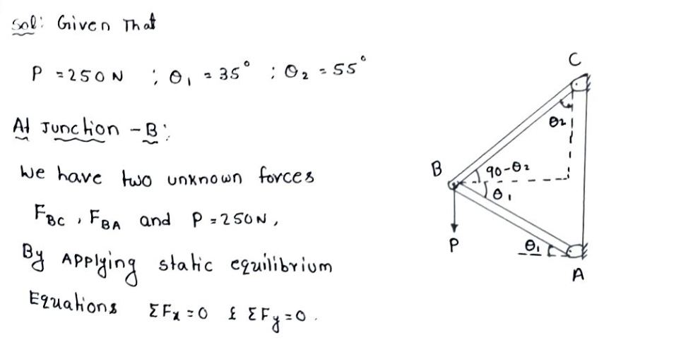
In this exercise, we will examine the forces in a truss system involving two members, \( BA \) and \( BC \). A downward load \( P \) of 250 N is applied at point \( B \). The challenge is to calculate the magnitudes of the loads supported by members \( BA \) and \( BC \).
**Problem Statement:**
A load \( P = 250 \, \text{N} \) is applied downward at point \( B \). It is supported by two truss members:
- Member \( BA \) forms an angle \( \theta_1 = 35^\circ \) with the horizontal axis.
- Member \( BC \) forms an angle \( \theta_2 = 55^\circ \) with the vertical axis.
**Objective:**
Calculate the magnitudes of the forces in members \( BA \) and \( BC \).
**Diagram Explanation:**
The diagram displays a triangular truss system:
- **Point \( A \)** is at the base where member \( BA \) is anchored.
- **Point \( B \)** is where the load \( P \) is applied.
- **Point \( C \)** is the top end where member \( BC \) is anchored vertically.
The load \( P \) acts vertically downward at point \( B \). The members \( BA \) and \( BC \) support this applied load.
**Parameters:**
| Parameter | Value | Units |
|-----------|-------|-------|
| \( P \) | 250 | N |
| \( \theta_1 \) | 35 | \( ^\circ \) |
| \( \theta_2 \) | 55 | \( ^\circ \) |
**Tasks:**
Calculate:
1. The magnitude of the force vector along \( BA \).
2. The magnitude of the force vector along \( BC \).
Use static equilibrium equations and trigonometric relations to find the solutions.
![### Analyzing Forces in a Structural System
In this exercise, we will analyze the forces in a structural system with two members, \( BA \) and \( BC \). The goal is to calculate the magnitudes of the loads supported by each member.
#### Problem Statement
A force \( P \) of 250 N is applied at point \( B \). Member \( BA \) makes an angle of \( \theta_1 = 35^\circ \) with the horizontal axis, while member \( BC \) makes an angle of \( \theta_2 = 55^\circ \) with the vertical axis. Determine the force vectors along members \( BA \) and \( BC \).
#### Diagram Description
- **Structural Members**: The diagram shows two connected members, \( BA \) and \( BC \), forming a triangular configuration.
- **Angles**:
- \( \theta_1 \) (35°) is the angle between member \( BA \) and the horizontal.
- \( \theta_2 \) (55°) is the angle between member \( BC \) and the vertical.
- **Force Application**: A downward force (P = 250 N) is applied at point \( B \).
#### Parameters and Units
| Parameter | Value | Units |
|-----------|-------|-------|
| \( P \) | 250 | N |
| \( \theta_1 \) | 35 | ° |
| \( \theta_2 \) | 55 | ° |
#### Calculations
To determine the magnitudes of the force vectors:
- **Magnitude along \( BA \)**: \[ \_\_\_ \, \text{N} \]
- **Magnitude along \( BC \)**: \[ \_\_\_ \, \text{N} \]
These values can be found using trigonometric relationships inherent in the described angles and forces.
This exercise is a fundamental problem in analyzing static structures, often encountered in fields such as civil and mechanical engineering. Understanding the force distribution provides insight into material selection and structural integrity.](/v2/_next/image?url=https%3A%2F%2Fcontent.bartleby.com%2Fqna-images%2Fquestion%2F6e7ba281-dd87-4688-be97-9abf26130e05%2F96174067-f499-4b6a-8c34-fae1948a7a5c%2Famgc1uq_processed.jpeg&w=3840&q=75)
Transcribed Image Text:### Analyzing Forces in a Structural System
In this exercise, we will analyze the forces in a structural system with two members, \( BA \) and \( BC \). The goal is to calculate the magnitudes of the loads supported by each member.
#### Problem Statement
A force \( P \) of 250 N is applied at point \( B \). Member \( BA \) makes an angle of \( \theta_1 = 35^\circ \) with the horizontal axis, while member \( BC \) makes an angle of \( \theta_2 = 55^\circ \) with the vertical axis. Determine the force vectors along members \( BA \) and \( BC \).
#### Diagram Description
- **Structural Members**: The diagram shows two connected members, \( BA \) and \( BC \), forming a triangular configuration.
- **Angles**:
- \( \theta_1 \) (35°) is the angle between member \( BA \) and the horizontal.
- \( \theta_2 \) (55°) is the angle between member \( BC \) and the vertical.
- **Force Application**: A downward force (P = 250 N) is applied at point \( B \).
#### Parameters and Units
| Parameter | Value | Units |
|-----------|-------|-------|
| \( P \) | 250 | N |
| \( \theta_1 \) | 35 | ° |
| \( \theta_2 \) | 55 | ° |
#### Calculations
To determine the magnitudes of the force vectors:
- **Magnitude along \( BA \)**: \[ \_\_\_ \, \text{N} \]
- **Magnitude along \( BC \)**: \[ \_\_\_ \, \text{N} \]
These values can be found using trigonometric relationships inherent in the described angles and forces.
This exercise is a fundamental problem in analyzing static structures, often encountered in fields such as civil and mechanical engineering. Understanding the force distribution provides insight into material selection and structural integrity.
Expert Solution
Step 1: Given that

Step by step
Solved in 3 steps with 3 images

Knowledge Booster


Learn more about
Need a deep-dive on the concept behind this application? Look no further. Learn more about this topic, civil-engineering and related others by exploring similar questions and additional content below.Recommended textbooks for you

Structural Analysis (10th Edition)
Civil Engineering
ISBN:
9780134610672
Author:
Russell C. Hibbeler
Publisher:
PEARSON

Principles of Foundation Engineering (MindTap Cou…
Civil Engineering
ISBN:
9781337705028
Author:
Braja M. Das, Nagaratnam Sivakugan
Publisher:
Cengage Learning
Structural Analysis (10th Edition)
Civil Engineering
ISBN:
9780134610672
Author:
Russell C. Hibbeler
Publisher:
PEARSON
Principles of Foundation Engineering (MindTap Cou…
Civil Engineering
ISBN:
9781337705028
Author:
Braja M. Das, Nagaratnam Sivakugan
Publisher:
Cengage Learning

Fundamentals of Structural Analysis
Civil Engineering
ISBN:
9780073398006
Author:
Kenneth M. Leet Emeritus, Chia-Ming Uang, Joel Lanning
Publisher:
McGraw-Hill Education


Traffic and Highway Engineering
Civil Engineering
ISBN:
9781305156241
Author:
Garber, Nicholas J.
Publisher:
Cengage Learning