In the Figure Below, determine the following: a. Xe b. The dc voltage across the input terminals 1 and 2 c. The dc voltage across R₂
In the Figure Below, determine the following: a. Xe b. The dc voltage across the input terminals 1 and 2 c. The dc voltage across R₂

Introductory Circuit Analysis (13th Edition)
13th Edition
ISBN:9780133923605
Author:Robert L. Boylestad
Publisher:Robert L. Boylestad
Chapter1: Introduction
Section: Chapter Questions
Problem 1P: Visit your local library (at school or home) and describe the extent to which it provides literature...

Related questions

Question
please show all work

Transcribed Image Text:### Exercise: Analyze the Electrical Circuit
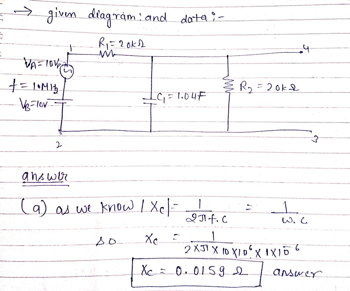
In the figure below, determine the following:
a. \( X_{C1} \)
b. The DC voltage across the input terminals 1 and 2
c. The DC voltage across \( R_1 \)
d. The DC voltage across \( R_2 \)
e. The DC voltage across \( C_1 \)
f. The peak-to-peak voltage across the input terminals 1 and 2
g. The approximate peak-to-peak voltage across the input terminals 3 and 4
h. The approximate peak-to-peak voltage across \( R_1 \)
#### Circuit Description
- \( R_1 = 20 \, k\Omega \)
- \( C_1 = 1.0 \, \mu F \)
- \( R_2 = 20 \, k\Omega \)
- \( V_A = 10 \, V_{p-p} \)
- Frequency \( f = 10 \, MHz \)
- \( V_B = 10 \, V \)
The circuit consists of a voltage source \( V_A \) with peak-to-peak voltage of 10 V and frequency of 10 MHz. It is connected in series with a resistor \( R_1 \), a capacitor \( C_1 \), and another resistor \( R_2 \).
This technical task aims at understanding both DC and AC characteristics of the described circuit.
Expert Solution
Step 1: given data and value of reactance of capacitor
given data and value of Xc

Step by step
Solved in 3 steps with 2 images

Knowledge Booster


Learn more about
Need a deep-dive on the concept behind this application? Look no further. Learn more about this topic, electrical-engineering and related others by exploring similar questions and additional content below.Recommended textbooks for you
Introductory Circuit Analysis (13th Edition)
Electrical Engineering
ISBN:
9780133923605
Author:
Robert L. Boylestad
Publisher:
PEARSON

Delmar's Standard Textbook Of Electricity
Electrical Engineering
ISBN:
9781337900348
Author:
Stephen L. Herman
Publisher:
Cengage Learning

Programmable Logic Controllers
Electrical Engineering
ISBN:
9780073373843
Author:
Frank D. Petruzella
Publisher:
McGraw-Hill Education
Introductory Circuit Analysis (13th Edition)
Electrical Engineering
ISBN:
9780133923605
Author:
Robert L. Boylestad
Publisher:
PEARSON
Delmar's Standard Textbook Of Electricity
Electrical Engineering
ISBN:
9781337900348
Author:
Stephen L. Herman
Publisher:
Cengage Learning
Programmable Logic Controllers
Electrical Engineering
ISBN:
9780073373843
Author:
Frank D. Petruzella
Publisher:
McGraw-Hill Education

Fundamentals of Electric Circuits
Electrical Engineering
ISBN:
9780078028229
Author:
Charles K Alexander, Matthew Sadiku
Publisher:
McGraw-Hill Education

Electric Circuits. (11th Edition)
Electrical Engineering
ISBN:
9780134746968
Author:
James W. Nilsson, Susan Riedel
Publisher:
PEARSON

Engineering Electromagnetics
Electrical Engineering
ISBN:
9780078028151
Author:
Hayt, William H. (william Hart), Jr, BUCK, John A.
Publisher:
Mcgraw-hill Education,