In the circuit below, the switch is closed at time t = 0 after being open for a long time. 1. Find v(t) for 0 < t. What is the RC time constant? At time t = 1 second, the switch is suddenly opened. 2. Find v(t) at t = 1 second right before the switch opens. [hint: a capacitor acts as an open circuit when it's in its steady state]. 3. Determine the time it takes the capacitor voltage to decay to 1/3 of its initial value.
In the circuit below, the switch is closed at time t = 0 after being open for a long time. 1. Find v(t) for 0 < t. What is the RC time constant? At time t = 1 second, the switch is suddenly opened. 2. Find v(t) at t = 1 second right before the switch opens. [hint: a capacitor acts as an open circuit when it's in its steady state]. 3. Determine the time it takes the capacitor voltage to decay to 1/3 of its initial value.

Introductory Circuit Analysis (13th Edition)
13th Edition
ISBN:9780133923605
Author:Robert L. Boylestad
Publisher:Robert L. Boylestad
Chapter1: Introduction
Section: Chapter Questions
Problem 1P: Visit your local library (at school or home) and describe the extent to which it provides literature...

Related questions
Question
Handwrite, more details
![### Problem Statement
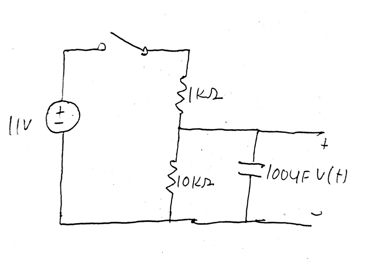
In the circuit below, the switch is closed at time \( t = 0 \) after being open for a long time.
1. Find \( v(t) \) for \( 0 < t \). What is the RC time constant?
At time \( t = 1 \) second, the switch is suddenly opened.
2. Find \( v(t) \) at \( t = 1 \) second right before the switch opens. [Hint: a capacitor acts as an open circuit when it’s in its steady state].
3. Determine the time it takes the capacitor voltage to decay to \( \frac{1}{3} \) of its initial value.
4. Find the instantaneous power dissipated by the circuit for all \( t > 1 \) second, as well as the total energy dissipated for all \( t > 1 \) second.
### Circuit Description
The circuit consists of:
- A voltage source of 11 V.
- A switch that controls the connection.
- A 1 kΩ resistor in series.
- A parallel combination of a 10 kΩ resistor and a 100 μF capacitor, connecting at the point where \( v(t) \) is measured.
### Diagram Explanation
The circuit diagram shows a simple RC series circuit with the following characteristics:
- The voltage source is connected to a 1 kΩ resistor, which then connects to a parallel combination of a 10 kΩ resistor and a 100 μF capacitor.
- The 11 V supply voltage feeds directly into these components.
- The switch controls the starting point of the circuit action described in the problem.
This setup is typical for analyzing transient response in RC circuits and involves solving for voltages and dissipated power over time.](/v2/_next/image?url=https%3A%2F%2Fcontent.bartleby.com%2Fqna-images%2Fquestion%2F099a9854-7cc3-46b9-a37c-ec0486b4a12a%2Fc288b59e-7a51-4dce-bf79-ae13c4dbed32%2Fakni73j_processed.png&w=3840&q=75)
Transcribed Image Text:### Problem Statement
In the circuit below, the switch is closed at time \( t = 0 \) after being open for a long time.
1. Find \( v(t) \) for \( 0 < t \). What is the RC time constant?
At time \( t = 1 \) second, the switch is suddenly opened.
2. Find \( v(t) \) at \( t = 1 \) second right before the switch opens. [Hint: a capacitor acts as an open circuit when it’s in its steady state].
3. Determine the time it takes the capacitor voltage to decay to \( \frac{1}{3} \) of its initial value.
4. Find the instantaneous power dissipated by the circuit for all \( t > 1 \) second, as well as the total energy dissipated for all \( t > 1 \) second.
### Circuit Description
The circuit consists of:
- A voltage source of 11 V.
- A switch that controls the connection.
- A 1 kΩ resistor in series.
- A parallel combination of a 10 kΩ resistor and a 100 μF capacitor, connecting at the point where \( v(t) \) is measured.
### Diagram Explanation
The circuit diagram shows a simple RC series circuit with the following characteristics:
- The voltage source is connected to a 1 kΩ resistor, which then connects to a parallel combination of a 10 kΩ resistor and a 100 μF capacitor.
- The 11 V supply voltage feeds directly into these components.
- The switch controls the starting point of the circuit action described in the problem.
This setup is typical for analyzing transient response in RC circuits and involves solving for voltages and dissipated power over time.
Expert Solution
Step 1
Since you have posted a question with multiple sub-parts, we will solve the first three sub-parts for you. To get the remaining sub-part solved please repost the complete question and mention the sub-parts to be solved.”
Given,

Step by step
Solved in 4 steps with 4 images

Recommended textbooks for you
Introductory Circuit Analysis (13th Edition)
Electrical Engineering
ISBN:
9780133923605
Author:
Robert L. Boylestad
Publisher:
PEARSON

Delmar's Standard Textbook Of Electricity
Electrical Engineering
ISBN:
9781337900348
Author:
Stephen L. Herman
Publisher:
Cengage Learning

Programmable Logic Controllers
Electrical Engineering
ISBN:
9780073373843
Author:
Frank D. Petruzella
Publisher:
McGraw-Hill Education
Introductory Circuit Analysis (13th Edition)
Electrical Engineering
ISBN:
9780133923605
Author:
Robert L. Boylestad
Publisher:
PEARSON
Delmar's Standard Textbook Of Electricity
Electrical Engineering
ISBN:
9781337900348
Author:
Stephen L. Herman
Publisher:
Cengage Learning
Programmable Logic Controllers
Electrical Engineering
ISBN:
9780073373843
Author:
Frank D. Petruzella
Publisher:
McGraw-Hill Education

Fundamentals of Electric Circuits
Electrical Engineering
ISBN:
9780078028229
Author:
Charles K Alexander, Matthew Sadiku
Publisher:
McGraw-Hill Education

Electric Circuits. (11th Edition)
Electrical Engineering
ISBN:
9780134746968
Author:
James W. Nilsson, Susan Riedel
Publisher:
PEARSON

Engineering Electromagnetics
Electrical Engineering
ISBN:
9780078028151
Author:
Hayt, William H. (william Hart), Jr, BUCK, John A.
Publisher:
Mcgraw-hill Education,