In terms of Vin, what is the output voltage Vout of the circuit shown? in 2 ΚΩ ww 2 V + 4 ΚΩ ww out
In terms of Vin, what is the output voltage Vout of the circuit shown? in 2 ΚΩ ww 2 V + 4 ΚΩ ww out

Introductory Circuit Analysis (13th Edition)
13th Edition
ISBN:9780133923605
Author:Robert L. Boylestad
Publisher:Robert L. Boylestad
Chapter1: Introduction
Section: Chapter Questions
Problem 1P: Visit your local library (at school or home) and describe the extent to which it provides literature...

Related questions

Question
![**Circuit Analysis Problem**
**Question:**
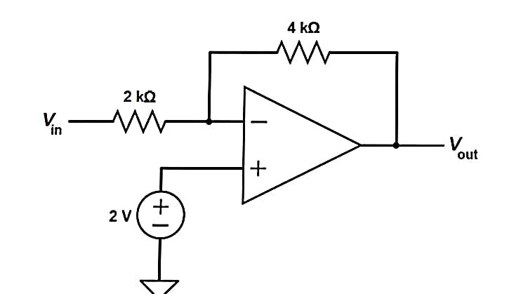
In terms of \( V_{\text{in}} \), what is the output voltage \( V_{\text{out}} \) of the circuit shown?
**Circuit Description:**
The circuit comprises the following components:
1. **Input Voltage (\( V_{\text{in}} \))**: The source voltage is connected to the left side of the circuit.
2. **Resistors**:
- A 2 kΩ resistor is connected directly in series with \( V_{\text{in}} \).
- A 4 kΩ resistor is part of the feedback loop connected from the output back to the inverting input of the op-amp.
3. **Operational Amplifier (Op-Amp)**:
- The op-amp has the inverting input connected through the 2 kΩ resistor and a non-inverting input connected to a 2V DC voltage source.
- The op-amp generates the output voltage \( V_{\text{out}} \).
4. **DC Voltage Source**:
- A 2V DC voltage source is connected to the non-inverting input of the op-amp.
**Analysis:**
This configuration forms a non-inverting op-amp with feedback, where the gain is determined by the resistors in the circuit. The output voltage (\( V_{\text{out}} \)) can be calculated by analyzing the op-amp equations and the resistive feedback network.
By using the formula for gain in a non-inverting operational amplifier configuration, one can derive the exact relationship between \( V_{\text{in}} \) and \( V_{\text{out}} \).
In this circuit, you can calculate the gain (\( G \)) using the resistor values:
\[ G = 1 + \left(\frac{R_{\text{feedback}}}{R_{\text{input}}}\right) = 1 + \left(\frac{4 \text{ k}\Omega}{2 \text{ k}\Omega}\right) = 3 \]
**Final Calculation for Output Voltage:**
The output voltage \( V_{\text{out}} \) in terms of the input voltage \( V_{\text{in}} \) and the DC offset is given by:
\[ V_{\text{out}} = 3(V_{\text{in}} + 2 \text{V}) \]
This expression helps to understand how changes in \( V_{\text](/v2/_next/image?url=https%3A%2F%2Fcontent.bartleby.com%2Fqna-images%2Fquestion%2Fd87dcd25-bea2-4b87-be07-9e8eae355a19%2F38deecda-da04-465a-94bc-4df571e6bc21%2F1o3n2nd_processed.png&w=3840&q=75)
Transcribed Image Text:**Circuit Analysis Problem**
**Question:**
In terms of \( V_{\text{in}} \), what is the output voltage \( V_{\text{out}} \) of the circuit shown?
**Circuit Description:**
The circuit comprises the following components:
1. **Input Voltage (\( V_{\text{in}} \))**: The source voltage is connected to the left side of the circuit.
2. **Resistors**:
- A 2 kΩ resistor is connected directly in series with \( V_{\text{in}} \).
- A 4 kΩ resistor is part of the feedback loop connected from the output back to the inverting input of the op-amp.
3. **Operational Amplifier (Op-Amp)**:
- The op-amp has the inverting input connected through the 2 kΩ resistor and a non-inverting input connected to a 2V DC voltage source.
- The op-amp generates the output voltage \( V_{\text{out}} \).
4. **DC Voltage Source**:
- A 2V DC voltage source is connected to the non-inverting input of the op-amp.
**Analysis:**
This configuration forms a non-inverting op-amp with feedback, where the gain is determined by the resistors in the circuit. The output voltage (\( V_{\text{out}} \)) can be calculated by analyzing the op-amp equations and the resistive feedback network.
By using the formula for gain in a non-inverting operational amplifier configuration, one can derive the exact relationship between \( V_{\text{in}} \) and \( V_{\text{out}} \).
In this circuit, you can calculate the gain (\( G \)) using the resistor values:
\[ G = 1 + \left(\frac{R_{\text{feedback}}}{R_{\text{input}}}\right) = 1 + \left(\frac{4 \text{ k}\Omega}{2 \text{ k}\Omega}\right) = 3 \]
**Final Calculation for Output Voltage:**
The output voltage \( V_{\text{out}} \) in terms of the input voltage \( V_{\text{in}} \) and the DC offset is given by:
\[ V_{\text{out}} = 3(V_{\text{in}} + 2 \text{V}) \]
This expression helps to understand how changes in \( V_{\text
Expert Solution
Step 1: Determination of given parameters,
The circuit diagram,

Step by step
Solved in 3 steps with 4 images

Knowledge Booster


Learn more about
Need a deep-dive on the concept behind this application? Look no further. Learn more about this topic, electrical-engineering and related others by exploring similar questions and additional content below.Recommended textbooks for you
Introductory Circuit Analysis (13th Edition)
Electrical Engineering
ISBN:
9780133923605
Author:
Robert L. Boylestad
Publisher:
PEARSON

Delmar's Standard Textbook Of Electricity
Electrical Engineering
ISBN:
9781337900348
Author:
Stephen L. Herman
Publisher:
Cengage Learning

Programmable Logic Controllers
Electrical Engineering
ISBN:
9780073373843
Author:
Frank D. Petruzella
Publisher:
McGraw-Hill Education
Introductory Circuit Analysis (13th Edition)
Electrical Engineering
ISBN:
9780133923605
Author:
Robert L. Boylestad
Publisher:
PEARSON
Delmar's Standard Textbook Of Electricity
Electrical Engineering
ISBN:
9781337900348
Author:
Stephen L. Herman
Publisher:
Cengage Learning
Programmable Logic Controllers
Electrical Engineering
ISBN:
9780073373843
Author:
Frank D. Petruzella
Publisher:
McGraw-Hill Education

Fundamentals of Electric Circuits
Electrical Engineering
ISBN:
9780078028229
Author:
Charles K Alexander, Matthew Sadiku
Publisher:
McGraw-Hill Education

Electric Circuits. (11th Edition)
Electrical Engineering
ISBN:
9780134746968
Author:
James W. Nilsson, Susan Riedel
Publisher:
PEARSON

Engineering Electromagnetics
Electrical Engineering
ISBN:
9780078028151
Author:
Hayt, William H. (william Hart), Jr, BUCK, John A.
Publisher:
Mcgraw-hill Education,