Determine the forces exerted at C and E on the tong BCE.
Chapter2: Loads On Structures
Section: Chapter Questions
Problem 1P
Related questions
Question

Transcribed Image Text:**Problem 6.141**
A steel ingot weighing 8000 lb is lifted by a pair of tongs as shown. Determine the forces exerted at C and E on the tong BCE.
---
This exercise involves analyzing the forces acting on a mechanical lifting device. A pair of tongs is used to lift a steel ingot weighing 8000 pounds. The objective is to calculate the specific forces exerted at specific points, labeled C and E, on the tong BCE. This type of problem typically involves understanding concepts of static equilibrium, force decomposition, and moments.
**Understanding the Problem:**
- **Weight of Ingot:** 8000 lb
- **Points of Interest:** C and E on the tong BCE
**Approach:**
1. **Free Body Diagram (FBD):**
- Draw an FBD representing the tong as a rigid body.
- Identify all acting forces, including the weight of the ingot and reaction forces at the points C and E.
2. **Equilibrium Equations:**
- Apply the conditions for static equilibrium: sum of forces in all directions should equal zero, and the sum of moments about any point should also equal zero.
- Use these equations to solve for the unknown forces at C and E.
**Applications:**
This problem is practical for understanding real-world applications like material handling in manufacturing, construction, or logistics, where understanding the proper application of forces ensures safety and efficacy in operations.

Transcribed Image Text:The diagram illustrates a mechanical lifting system supporting an 8000 lb weight, suspended by a series of bars and joints.
- The system consists of a pair of crossed links: \( A \) to \( C \) and \( B \) to \( D \), with arrows at the top indicating points \( A \) and \( B \) with upward forces.
- The distance between points \( A \) and \( B \) is 14 inches.
- The horizontal span from point \( C \) to \( D \) is 45 inches.
- Vertical distances are indicated: from \( A \) to \( C \) and \( B \) to \( D \) is 35 inches, and from \( C \) (or \( D \)) to the base points \( E \) and \( F \) is 55 inches.
- The weight is directly attached at the bottom between points \( E \) and \( F \), which are 55 inches apart horizontally.
- The complete assembly shows a mechanical structure that likely operates in a symmetrical manner to balance and lift the central load.
This diagram (Fig. P6.141) aids in understanding the geometric and force relationships within the lift mechanism.
Expert Solution
This question has been solved!
Explore an expertly crafted, step-by-step solution for a thorough understanding of key concepts.
This is a popular solution!
Trending now
This is a popular solution!
Step by step
Solved in 3 steps with 3 images

Follow-up Questions
Read through expert solutions to related follow-up questions below.
Follow-up Question

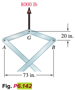
Transcribed Image Text:6.142 If the toggle shown is added to the tongs of Prob. 6.141 and the load is
lifted by applying a single force at G, determine the forces exerted at
C and E on the tong BCE.

Transcribed Image Text:A
8000 lb
G
-73 in.-
Fig. P6.142
B
20 in.
Solution
Knowledge Booster
Learn more about
Need a deep-dive on the concept behind this application? Look no further. Learn more about this topic, civil-engineering and related others by exploring similar questions and additional content below.Recommended textbooks for you


Structural Analysis (10th Edition)
Civil Engineering
ISBN:
9780134610672
Author:
Russell C. Hibbeler
Publisher:
PEARSON

Principles of Foundation Engineering (MindTap Cou…
Civil Engineering
ISBN:
9781337705028
Author:
Braja M. Das, Nagaratnam Sivakugan
Publisher:
Cengage Learning


Structural Analysis (10th Edition)
Civil Engineering
ISBN:
9780134610672
Author:
Russell C. Hibbeler
Publisher:
PEARSON

Principles of Foundation Engineering (MindTap Cou…
Civil Engineering
ISBN:
9781337705028
Author:
Braja M. Das, Nagaratnam Sivakugan
Publisher:
Cengage Learning

Fundamentals of Structural Analysis
Civil Engineering
ISBN:
9780073398006
Author:
Kenneth M. Leet Emeritus, Chia-Ming Uang, Joel Lanning
Publisher:
McGraw-Hill Education


Traffic and Highway Engineering
Civil Engineering
ISBN:
9781305156241
Author:
Garber, Nicholas J.
Publisher:
Cengage Learning