I need help using KVL to measure the voltage drops across the following resistors, comparing to my measured values in multisim.
I need help using KVL to measure the voltage drops across the following resistors, comparing to my measured values in multisim.

Introductory Circuit Analysis (13th Edition)
13th Edition
ISBN:9780133923605
Author:Robert L. Boylestad
Publisher:Robert L. Boylestad
Chapter1: Introduction
Section: Chapter Questions
Problem 1P: Visit your local library (at school or home) and describe the extent to which it provides literature...

Related questions

Question
I need help using KVL to measure the voltage drops across the following resistors, comparing to my measured values in multisim.

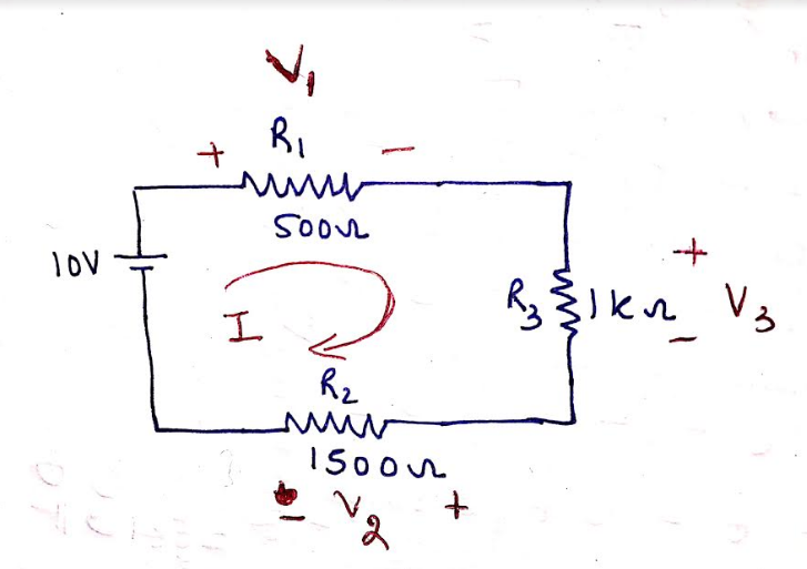
Transcribed Image Text:The image depicts an electronic circuit diagram with three resistors and a power source, along with three voltmeters (labeled XMM1, XMM2, and XMM3), measuring the voltage across different parts of the circuit.
### Circuit Description:
- **Power Source (V1):** Supplies 10V to the circuit.
- **Resistors:**
- **R1:** 500Ω
- **R2:** 1500Ω
- **R3:** 1kΩ (1000Ω)
### Multimeter Readings:
- **Multimeter XMM1:** Measures the voltage across R1, showing a reading of 1.667V.
- **Multimeter XMM2:** Measures the voltage across R3, displaying a voltage of 3.333V.
- **Multimeter XMM3:** Measures the voltage after R2, showing a reading of 5V.
### Explanation:
- **Total Voltage:** The combined voltage drops (from XMM1 and XMM2) and the remaining voltage measured by XMM3 should add up to the power supply voltage (10V).
- **Ohm’s Law Application:** The voltage drop across each resistor is consistent with Ohm’s Law (V = IR), considering the resistances provided and voltage measurements.
This setup appears to be a series circuit, where the total voltage is divided among the resistors according to their resistance values.
Expert Solution
Step 1
Draw the circuit first:
Apply the KVL and find the value of I:
Step 2 Now find the value across each resistor
First find voltage V1 across R1 resistor:
Now find voltage V2 across R2 resistor:
Now find voltage V3 across R3 resistor:

Step by step
Solved in 3 steps with 1 images

Knowledge Booster


Learn more about
Need a deep-dive on the concept behind this application? Look no further. Learn more about this topic, electrical-engineering and related others by exploring similar questions and additional content below.Recommended textbooks for you
Introductory Circuit Analysis (13th Edition)
Electrical Engineering
ISBN:
9780133923605
Author:
Robert L. Boylestad
Publisher:
PEARSON

Delmar's Standard Textbook Of Electricity
Electrical Engineering
ISBN:
9781337900348
Author:
Stephen L. Herman
Publisher:
Cengage Learning

Programmable Logic Controllers
Electrical Engineering
ISBN:
9780073373843
Author:
Frank D. Petruzella
Publisher:
McGraw-Hill Education
Introductory Circuit Analysis (13th Edition)
Electrical Engineering
ISBN:
9780133923605
Author:
Robert L. Boylestad
Publisher:
PEARSON
Delmar's Standard Textbook Of Electricity
Electrical Engineering
ISBN:
9781337900348
Author:
Stephen L. Herman
Publisher:
Cengage Learning
Programmable Logic Controllers
Electrical Engineering
ISBN:
9780073373843
Author:
Frank D. Petruzella
Publisher:
McGraw-Hill Education

Fundamentals of Electric Circuits
Electrical Engineering
ISBN:
9780078028229
Author:
Charles K Alexander, Matthew Sadiku
Publisher:
McGraw-Hill Education

Electric Circuits. (11th Edition)
Electrical Engineering
ISBN:
9780134746968
Author:
James W. Nilsson, Susan Riedel
Publisher:
PEARSON

Engineering Electromagnetics
Electrical Engineering
ISBN:
9780078028151
Author:
Hayt, William H. (william Hart), Jr, BUCK, John A.
Publisher:
Mcgraw-hill Education,