I a) Design a noninverting amplifier with a gain of 100 using ideal op amps and practical values of resistors. Draw a schematic of your circuit showing input, output, and all resistor values. b) If the op amp in part la) is not ideal but has an input offset voltage of +/- 5mV and input bias currents of 100nA and the source resistance at the input is 50k ohms, then what is the range of the output voltage when the input is zero volts? Show and explain our calculations.
I a) Design a noninverting amplifier with a gain of 100 using ideal op amps and practical values of resistors. Draw a schematic of your circuit showing input, output, and all resistor values. b) If the op amp in part la) is not ideal but has an input offset voltage of +/- 5mV and input bias currents of 100nA and the source resistance at the input is 50k ohms, then what is the range of the output voltage when the input is zero volts? Show and explain our calculations.

Introductory Circuit Analysis (13th Edition)
13th Edition
ISBN:9780133923605
Author:Robert L. Boylestad
Publisher:Robert L. Boylestad
Chapter1: Introduction
Section: Chapter Questions
Problem 1P: Visit your local library (at school or home) and describe the extent to which it provides literature...

Related questions

Question
1 please

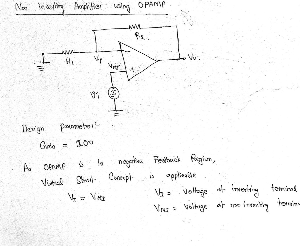
Transcribed Image Text:1 a) Design a noninverting amplifier with a gain of 100 using ideal op amps and practical
values of resistors. Draw a schematic of your circuit showing input, output, and all
resistor values.
b) If the op amp in part la) is not ideal but has an input offset voltage of +/- 5mV and
input bias currents of 100nA and the source resistance at the input is 50k ohms, then what
is the range of the output voltage when the input is zero volts? Show and explain our
calculations.
2 a) Calculate the output voltage in the circuit below using superposition. Assume that
the op amps are ideal and that Va-50mV and Vb-30mV.
b) What is common mode rejection ratio (CMRR) and why is it important?
c) If the circuit below has 80dB of CMRR and there is IV of common mode signal, then
how much of the common mode signal will be present at the output?
20K
ak
LOK
3. Find the output voltage v, in each of the 3 circuits below and explain how you found it.
Assume all op amps are ideal.
No
IDK
100ml
10K3
100,
jok
10 ml
10k
20k
www
20k
MELONE
N₂
10K
20-V
d. Draw the circuit diagram for the 3 op amp instrumentation amplifier and show appropriate
values for all the resistors so that the amplification of differential signals is 100.
e. What is the primary advantage of this configuration and what is required of the resistors in
order to achieve this benefic? Why is this benefit essential to the practical problem of amplifying
real transducer signals?
f. If the input voltage is set to zero in the circuit of b, what is the maximum range of the output
voltage if the input offset voltage maximum value is +/- 8mV and the input bias current
maximum is 200 nanoamps?
Expert Solution
Step 1

Step by step
Solved in 5 steps with 5 images

Knowledge Booster


Learn more about
Need a deep-dive on the concept behind this application? Look no further. Learn more about this topic, electrical-engineering and related others by exploring similar questions and additional content below.Recommended textbooks for you
Introductory Circuit Analysis (13th Edition)
Electrical Engineering
ISBN:
9780133923605
Author:
Robert L. Boylestad
Publisher:
PEARSON

Delmar's Standard Textbook Of Electricity
Electrical Engineering
ISBN:
9781337900348
Author:
Stephen L. Herman
Publisher:
Cengage Learning

Programmable Logic Controllers
Electrical Engineering
ISBN:
9780073373843
Author:
Frank D. Petruzella
Publisher:
McGraw-Hill Education
Introductory Circuit Analysis (13th Edition)
Electrical Engineering
ISBN:
9780133923605
Author:
Robert L. Boylestad
Publisher:
PEARSON
Delmar's Standard Textbook Of Electricity
Electrical Engineering
ISBN:
9781337900348
Author:
Stephen L. Herman
Publisher:
Cengage Learning
Programmable Logic Controllers
Electrical Engineering
ISBN:
9780073373843
Author:
Frank D. Petruzella
Publisher:
McGraw-Hill Education

Fundamentals of Electric Circuits
Electrical Engineering
ISBN:
9780078028229
Author:
Charles K Alexander, Matthew Sadiku
Publisher:
McGraw-Hill Education

Electric Circuits. (11th Edition)
Electrical Engineering
ISBN:
9780134746968
Author:
James W. Nilsson, Susan Riedel
Publisher:
PEARSON

Engineering Electromagnetics
Electrical Engineering
ISBN:
9780078028151
Author:
Hayt, William H. (william Hart), Jr, BUCK, John A.
Publisher:
Mcgraw-hill Education,