How could I find the current and voltage in this circuit (io and vo)?
How could I find the current and voltage in this circuit (io and vo)?

Introductory Circuit Analysis (13th Edition)
13th Edition
ISBN:9780133923605
Author:Robert L. Boylestad
Publisher:Robert L. Boylestad
Chapter1: Introduction
Section: Chapter Questions
Problem 1P: Visit your local library (at school or home) and describe the extent to which it provides literature...

Related questions
Question
100%
How could I find the current and voltage in this circuit (io and vo)?

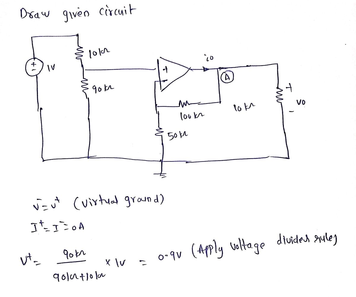
Transcribed Image Text:### Circuit Diagram Analysis
The diagram illustrates an operational amplifier circuit with several resistors and a voltage source. The key components and their connections are described below:
1. **Voltage Source**:
- A 1 V DC voltage source is present on the left side of the circuit.
2. **Resistors**:
- There are five resistors in the circuit:
- A 10 kΩ resistor is connected to the top of the voltage source.
- A 90 kΩ resistor is in series with the 10 kΩ resistor.
- A 100 kΩ resistor is positioned in the feedback loop of the operational amplifier.
- A 50 kΩ resistor is connected to the inverting input of the operational amplifier and to the ground.
- Another 10 kΩ resistor is connected at the output side of the op-amp leading to the output voltage \( v_o \).
3. **Operational Amplifier (Op-Amp)**:
- The op-amp has non-inverting (+) and inverting (-) inputs.
- The output of the op-amp is indicated as \( i_o \).
- The feedback loop is formed by the 100 kΩ resistor connecting the output back to the inverting input.
4. **Output**:
- The output voltage \( v_o \) is measured across the rightmost 10 kΩ resistor.
This configuration suggests a classic inverting amplifier setup where the feedback and input resistors determine the gain of the amplifier. The specific values of the resistors affect the gain and stability of the circuit.
Expert Solution
Step 1

Step by step
Solved in 2 steps with 2 images

Knowledge Booster


Learn more about
Need a deep-dive on the concept behind this application? Look no further. Learn more about this topic, electrical-engineering and related others by exploring similar questions and additional content below.Recommended textbooks for you
Introductory Circuit Analysis (13th Edition)
Electrical Engineering
ISBN:
9780133923605
Author:
Robert L. Boylestad
Publisher:
PEARSON

Delmar's Standard Textbook Of Electricity
Electrical Engineering
ISBN:
9781337900348
Author:
Stephen L. Herman
Publisher:
Cengage Learning

Programmable Logic Controllers
Electrical Engineering
ISBN:
9780073373843
Author:
Frank D. Petruzella
Publisher:
McGraw-Hill Education
Introductory Circuit Analysis (13th Edition)
Electrical Engineering
ISBN:
9780133923605
Author:
Robert L. Boylestad
Publisher:
PEARSON
Delmar's Standard Textbook Of Electricity
Electrical Engineering
ISBN:
9781337900348
Author:
Stephen L. Herman
Publisher:
Cengage Learning
Programmable Logic Controllers
Electrical Engineering
ISBN:
9780073373843
Author:
Frank D. Petruzella
Publisher:
McGraw-Hill Education

Fundamentals of Electric Circuits
Electrical Engineering
ISBN:
9780078028229
Author:
Charles K Alexander, Matthew Sadiku
Publisher:
McGraw-Hill Education

Electric Circuits. (11th Edition)
Electrical Engineering
ISBN:
9780134746968
Author:
James W. Nilsson, Susan Riedel
Publisher:
PEARSON

Engineering Electromagnetics
Electrical Engineering
ISBN:
9780078028151
Author:
Hayt, William H. (william Hart), Jr, BUCK, John A.
Publisher:
Mcgraw-hill Education,