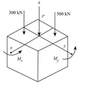
Hi, i was wonderwing why with the normal stress at B the moment Mx * Cy is minus. can you explain how to set up the correct equation for the normal stress. Because often i had a correct answer but the minus and pluses different.
Hi, i was wonderwing why with the normal stress at B the moment Mx * Cy is minus. can you explain how to set up the correct equation for the normal stress. Because often i had a correct answer but the minus and pluses different.
Chapter2: Loads On Structures
Section: Chapter Questions
Problem 1P
Related questions
Question
100%
Hi, i was wonderwing why with the normal stress at B the moment Mx * Cy is minus. can you explain how to set up the correct equation for the normal stress. Because often i had a correct answer but the minus and pluses different.

Transcribed Image Text:Determine the normal stress (A) at point A using the relation:
0A = +²+M₁²₁ (4)
Here, P is the vertical load acting, A is the cross section area, I, is the moment of inertia about x axis, I, is the
moment of inertia about y axis, c, is the distance from point A to the origin along y axis, c, is the distance
from point A to the origin along x axis, M, is the moment along x axis, and My moment alongy axis.
Substitute -800 x 10³ N for P, 0.09 m² for A, 35 x 10³ Nm for M, 0.675 x 10-³ m² for I, 0.675 x 10-³ m²
for Iy, 20 x 10³ N-m for My, 0.15 m for cy, and 0.15 m for c, in Equation (4).
-800(10³)
GA =
0.09
(35x10³)x0.15
0.675 (10³)
20x10²x0.15
0.675(10-³)
= 3.33333 MPa (T)
Hence, the normal stress (A) at corner A of the column is 3.33 MPa (T).
Determine the normal stress (8) at point B using the relation:
Mycy
(5)
08 = +
Here, P is the vertical load acting, A is the cross section area, I, is the moment of inertia about x axis, I, is the
moment of inertia about y axis, cy is the distance from point A to the origin along y axis, c, is the distance
from point A to the origin along x axis, M, is the moment along x axis, and My moment alongy axis.
Substitute -800 x 10³ N for P, 0.09 m² for A, 35 x 10³ Nm for Mx, 0.675 x 10-³ m² for I, 0.675 x 10-³ m²
for Iy, 20 × 10³ N-m for My, 0.15 m for cy, and 0.15 m for cx in Equation (5).
(35x10³)x0.15
0.675 (10-³)
--800(10³)
0.09
20x10²x0.15
0.675 (10³)
= -12.22 MPa
= 12.22 MPa (C)
Hence, the normal stress (8) at corner B of the column is 12.2 MPa (C).
OB =

Transcribed Image Text:Show the diagram of direction of force and moment as shown in Figure 1.
300 KN
Mx
Z
500 KN
-800 P
P = -800 KN
My
J
Figure 1
Let the negative sign of the force indicates the direction of the force acting downward M, and net moment
along y at My.
Calculate the resultant force acting the center of block due to vertical loads.
Σ F, = (FR),
-500-300 = P
Find the value of moment acting on block along x-axis.
300 (0.05)-500 (0.1) = Mx
15 - 50 = M,
M₂ = -35 kN - m
Expert Solution
Step 1
- From figure given below it is clear that the direction of moment about x-axis (Mx) and y-axis (My) is in anticlockwise direction.

Step by step
Solved in 2 steps with 3 images

Knowledge Booster
Learn more about
Need a deep-dive on the concept behind this application? Look no further. Learn more about this topic, civil-engineering and related others by exploring similar questions and additional content below.Recommended textbooks for you


Structural Analysis (10th Edition)
Civil Engineering
ISBN:
9780134610672
Author:
Russell C. Hibbeler
Publisher:
PEARSON

Principles of Foundation Engineering (MindTap Cou…
Civil Engineering
ISBN:
9781337705028
Author:
Braja M. Das, Nagaratnam Sivakugan
Publisher:
Cengage Learning


Structural Analysis (10th Edition)
Civil Engineering
ISBN:
9780134610672
Author:
Russell C. Hibbeler
Publisher:
PEARSON

Principles of Foundation Engineering (MindTap Cou…
Civil Engineering
ISBN:
9781337705028
Author:
Braja M. Das, Nagaratnam Sivakugan
Publisher:
Cengage Learning

Fundamentals of Structural Analysis
Civil Engineering
ISBN:
9780073398006
Author:
Kenneth M. Leet Emeritus, Chia-Ming Uang, Joel Lanning
Publisher:
McGraw-Hill Education


Traffic and Highway Engineering
Civil Engineering
ISBN:
9781305156241
Author:
Garber, Nicholas J.
Publisher:
Cengage Learning