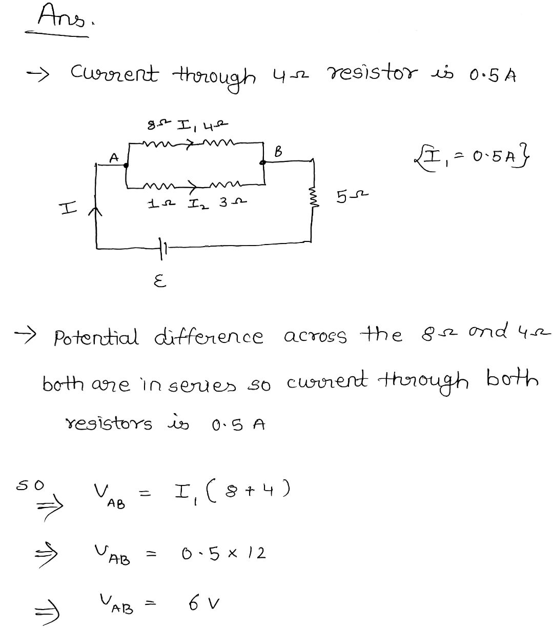
For the circuit shown in the figure, what is the emf (x) for the battery if current through the 4Ω resistor is 0.5A? ΑΛΛΑ ΜΑΛΑ 8 Ω 4 Ω ΑΝΑ 1Ω ε 3 Ω Α 5 Ω
Q: Three resistors, R1 = 2.09 Ω, R2 = 4.77 Ω, and R3 = 6.55 Ω are connected by ideal metal wires, as…
A:
Q: Please don't provide handwritten solution ....
A: Solution : Given circuit 7Ω, 3Ω and 4Ω are series then it becomes 7+3+4=14Ω Then circuit…
Q: The circuit in the figure is composed of two batteries (E, = 8 V and E, = 4 V) and four resistors…
A: Given that:- E1=8V and E2=4V R1=110 ohm R2=R3=40 ohm R4=50 ohm
Q: cult shown in the figure, both meters are idealized and the ammeter reads 0.30 A. What is the emf…
A: We are given ammeter reading. We first find the voltage across this resistor. This will be same…
Q: The circuit in the figure is composed of two batteries (E, = 8 V and ɛ2 = 4 V) and four resistors…
A: Given: R1 = 110 Ω, R2 = 40 Ω, R3 = 40 Ω, and R4 = 50 Ω
Q: 3Ω batt V V batt batt 6Ω 6Ω Circuit A Circuit B Circuit C In which circuit will the current through…
A:
Q: 76. Load R1 R2 R3 Total Resistance Voltage 20 Ω 25 Ω 30 02 Et R1 www R2 R3 www What is the total…
A: We have to find the total resistance for the given parallel resistance connection.
Q: ει 0.10 Ω R, 5.0 Ω E2, R 20 Ω R a 0.50 Ω 40 Ω 0.20 Ω R 78 Ω E4 E3 1 0.05 Ω h
A: Given: E1 = 21V E2 = 46V E3 = 5.5V E4 = 43V I1 = -0.42Amp. Applying Kirchhoff law of junction for…
Q: I I3 I4 Is Source Variables Load #1 Load #2 Load #3 Load #4 Load #5 (Total) Δν 15.0 2 15.0 2 15.0 N…
A:
Q: The following circuit has an ideal battery of potential difference 15.16V and R1 has a resistance of…
A: When circuit is hooked up for a long time then capacitor get fully charged and steady state will be…
Q: In the circuit given below, R= 55 Q. Find v, v2, and v3 using nodal analysis. 240 V 20i 20 Ω R 10 2…
A: Solution-
Q: How much current, in mA, flows through the resistor labeled R2? The battery shown provides a…
A:
Q: € = 30V b 15 μF 3 μF 7.5 μF 4 μF 12 μF 6 μF Consider the circuit shown in the figure. What is the…
A: Given : Circuit is given To find : Charge for the 4 μF capacitor
Q: 24.0 V 12.0 V + I Μ R₁ 4.00 Ω 13 3.00 Ω 5.00 Ω Μ R₂
A:
Q: The diagram shows a circuit where R1 = 4.00 Ω, R2 = 5.00 Ω, R3 = 4.00 Ω, V1 = 29.60 V, V2 = 21.40 V,…
A:
Q: What is the voltage,in V, across the resistor labeled R3? The battery shown provides a potential…
A: According to the circuit diagram, the resistors R3 and R4 are connected in parallel and their…
Q: A.) What is the current I? B.) How much power is dissipated by the unknown resistor R? You should…
A: See below
Q: A 260-V emf is connected to the terminals A and B. Here,V = 260V, R1 = 16 Ω, and R2 = 19Ω. What is…
A:
Q: What is the equivalent resistance of this circuit? R1= 13 kΩ. All other resistor values are…
A:
Q: The equivalent resistance of this circuit is 2.00 N 18.0 V 3.000 1.00 N Li 4.00 N 10 A 110 60 6.75 A
A: Let R1 = 2.00 Ω R2 = 3.00 Ω R3 = 1.00 Ω R4 = 4.00 Ω
Q: In the figure below, the battery emf labeled ɛ1 = 5.0 V. Determine the resistance of the resistor…
A: We need to apply Kirchhoff's laws to solve for the resistance R in circuit.
Q: The 10 Ω resistor in (Figure 1) is dissipating 36 W of power. How much power is the 5.0 Ω…
A:


Step by step
Solved in 4 steps with 4 images

- A 267-V emf is connected to the terminals A and B. Here,V = 267V, R1 = 14 Ω, and R2 = 19Ω. What is the current in the 14-Ω resistor?The figure shows a simple RC circuit consisting of a 100.0 V battery in series with a C = 10.0 μ F capacitor and a R = 4.3 × 10⁵ resistor. Initially, the switch S is open and the capacitor is uncharged. 100.0 V A) 1.1 x 10-³ C B) 2.9 × 10⁻³ C C) 3.7 x 10⁴ C D) 5.2 x 10⁻⁴ C E) 6.6 × 10⁴ C I S R 10.0 µF How much charge q is on the capacitor 2.0 s after the switch is closed? (Hint: First compute the final charge on the capacitor and the RC circuit's time constant.)What is the resistance (in ohm) of the light bulb if it glows with full brightness when connected to the battery? 12.5 watts d C а 2.50 V 2.00 Zero 5.00 0.500
- In the circuit shown below, the capacitor is initially uncharged. What is the current long after closing the switch? 12 V Ozero ○ 1200 mA ○ 1.2 A ○ 1.2 mA ww 10 ΚΩ 100 μFWhat is the equivalent capacitance of the circuit? 2 F O 0.67 F O 15 F O 3.7 F O 4.5 F 3 F 1 F 3 V HoloThe circuit to the right consists of a battery (V0=4.50 V) and five resistors (?1=611 Ω, R2=582 Ω, R3=163 Ω, R4=534 Ω, and R5=665 Ω). Determine the current passing through each of the specified points IH, IG, and IE in mA