for problems 13.1 through 13.6 use the virtual-work method to deteermine the deflection of each of the joints marked on the trusses shown in the accompaning illistrations. The circled figures are areas in square inches and E=29x10^6 psi unless otherwise indicated. the areas are 4, 4,
for problems 13.1 through 13.6 use the virtual-work method to deteermine the deflection of each of the joints marked on the trusses shown in the accompaning illistrations. The circled figures are areas in square inches and E=29x10^6 psi unless otherwise indicated. the areas are 4, 4,

Chapter2: Loads On Structures
Section: Chapter Questions
Problem 1P

Related questions

Question
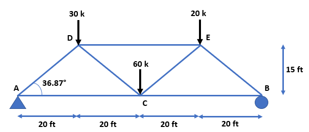
for problems 13.1 through 13.6 use the virtual-work method to deteermine the deflection of each of the joints marked on the trusses shown in the accompaning illistrations. The circled figures are areas in square inches and E=29x10^6 psi unless otherwise indicated. the areas are 4, 4, 4, 4, 4 on the outside with the two in the middle being 2 (as shown in the picture- the circled numbers).

Transcribed Image Text:The image shows a diagram of a truss structure used in engineering and architecture education. Here’s a detailed breakdown:
- **Truss Design**: The truss is composed of multiple members connected at joints, forming triangular units which provide stability.
- **Length and Support**: The total length of the truss is 80 feet, divided into two sections of 40 feet each. It is supported on the left by a fixed support and on the right by a roller support.
- **Loads**:
- A central downward force of 60 kips (kilopounds) is applied at joint \( L_2 \).
- Additional forces include 30 kips and 20 kips acting downward at two different joints to the right of \( L_2 \).
- **Angles and Triangular Units**:
- The truss includes several triangular sections which add to the structural integrity.
- The vertical distance from the base to the peak of the truss is 15 feet at joint \( L_4 \).
- **Labeling**: Each member of the truss is labeled with a number \( (4) \), indicating their importance or perhaps denoting equal lengths or properties within those members.
This diagram aids in understanding load distribution and stability in a truss system, useful for engineering students learning about structural design.
Expert Solution
Step 1 Given

Step by step
Solved in 8 steps with 14 images

Knowledge Booster


Learn more about
Need a deep-dive on the concept behind this application? Look no further. Learn more about this topic, civil-engineering and related others by exploring similar questions and additional content below.Recommended textbooks for you

Structural Analysis (10th Edition)
Civil Engineering
ISBN:
9780134610672
Author:
Russell C. Hibbeler
Publisher:
PEARSON

Principles of Foundation Engineering (MindTap Cou…
Civil Engineering
ISBN:
9781337705028
Author:
Braja M. Das, Nagaratnam Sivakugan
Publisher:
Cengage Learning
Structural Analysis (10th Edition)
Civil Engineering
ISBN:
9780134610672
Author:
Russell C. Hibbeler
Publisher:
PEARSON
Principles of Foundation Engineering (MindTap Cou…
Civil Engineering
ISBN:
9781337705028
Author:
Braja M. Das, Nagaratnam Sivakugan
Publisher:
Cengage Learning

Fundamentals of Structural Analysis
Civil Engineering
ISBN:
9780073398006
Author:
Kenneth M. Leet Emeritus, Chia-Ming Uang, Joel Lanning
Publisher:
McGraw-Hill Education


Traffic and Highway Engineering
Civil Engineering
ISBN:
9781305156241
Author:
Garber, Nicholas J.
Publisher:
Cengage Learning