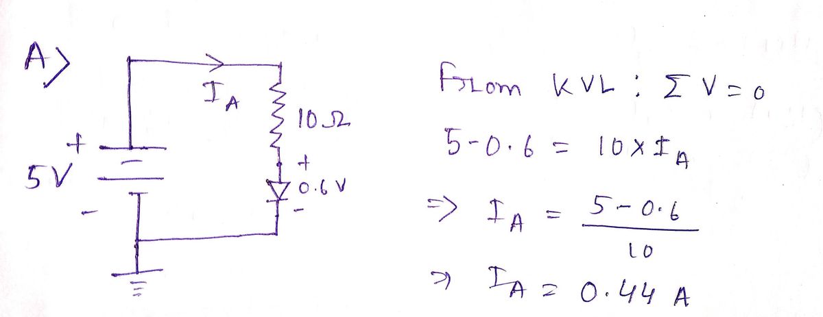
Find the approximate current in each of the following cireuits. Assume ideal 4) silicon diodes with Vp =0.6V. B SV 100? 5V 1 kf? E SV 1002 0.5 V 100? SV ww- ww ww
Find the approximate current in each of the following cireuits. Assume ideal 4) silicon diodes with Vp =0.6V. B SV 100? 5V 1 kf? E SV 1002 0.5 V 100? SV ww- ww ww
Question

Transcribed Image Text:### Problem Statement
4) Find the approximate current in each of the following circuits. Assume ideal silicon diodes with \( V_D = 0.6 \, \text{V} \).
### Circuit Descriptions
**Circuit A**:
- Voltage Source: 5 V
- Resistor: 10 Ω
- Diode in series with the resistor.
**Circuit B**:
- Voltage Source: 5 V
- Resistor: 100 Ω
- Diode in series with the resistor.
**Circuit C**:
- Voltage Source: 5 V
- Resistor: 1 kΩ
- Diode in series with the resistor.
**Circuit D**:
- Voltage Source: 5 V
- Resistor: 100 Ω
- Diode in series with the resistor, but polarity not shown differently than B.
**Circuit E**:
- Voltage Source: 0.5 V
- Resistor: 100 Ω
- Diode in series with the resistor.
**Circuit F**:
- Voltage Source: 5 V
- Only a diode present, no resistor.
### Explanation of Components
- **Voltage Source (V)**: Provides electrical energy for the circuit.
- **Resistor (Ω)**: Limits the current flowing through the circuit.
- **Diode**: Allows current to flow in one direction when forward-biased (above \( V_D \)).
### Analyzing the Circuits
For each circuit, calculate the current using Ohm's Law (\( I = \frac{V - V_D}{R} \)), where \( I \) is current, \( V \) is the voltage of the source, and \( V_D \) is the forward voltage drop of the diode:
- **A, B, C, D**: Calculate using the given resistor values.
- **E**: Since the source voltage (0.5 V) is less than \( V_D \), no current flows.
- **F**: Ideal diode conducts if forward-biased, current depends on load not specified directly.
Expert Solution
Step 1

Step by step
Solved in 3 steps with 2 images
