Find RT, Is, 1, 12, Ix, V1, V2, and the power absorbed by the 6 ohm resistor. RT 32 + 36V 8Ω 82
![**Circuit Analysis Problem**
In this circuit analysis exercise, you are required to find several parameters of the circuit shown in the diagram, including the total resistance and various current and voltage values, as well as the power absorbed by a specific resistor.
**Circuit Diagram Description:**
- The circuit consists of a 36V power supply connected to a network of resistors.
- At the top left, a 3Ω resistor is connected in series with the source voltage.
- Beyond this resistor, the circuit splits into two branches.
- One branch contains two 8Ω resistors in series.
- The other branch includes a parallel combination of a 6Ω and 3Ω resistor.
- Voltage across the 3Ω resistor is indicated by \( V_1 \), while the voltage across the 3Ω parallel resistor is \( V_2 \).
- Currents flowing through the different paths are labeled \( I_S \), \( I_1 \), \( I_2 \), and \( I_X \).
**Parameters to Determine:**
1. \( R_T \) = Total resistance of the circuit.
2. \( I_S \) = Source current.
3. \( I_1 \) = Current through the 6Ω resistor.
4. \( I_2 \) = Current through the series 8Ω resistors.
5. \( I_X \) = Current through the 3Ω resistor in parallel.
6. \( V_1 \) = Voltage across the 3Ω resistor at the top of the circuit.
7. \( V_2 \) = Voltage across the 3Ω resistor in parallel.
8. \( P_{6\Omega} \) = Power absorbed by the 6Ω resistor.
Complete the calculations for each of these parameters to properly analyze and understand the behavior of the circuit.](/v2/_next/image?url=https%3A%2F%2Fcontent.bartleby.com%2Fqna-images%2Fquestion%2F6fa7ac50-e43d-4267-956c-145cd19bd43c%2Fe14b8781-b871-4b7f-93e2-721e1e494cf0%2Frj3oygo_processed.png&w=3840&q=75)
![](/static/compass_v2/shared-icons/check-mark.png)
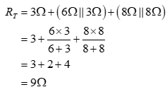
In circuit shown in question, the 6Ω resistor is in parallel with 3Ω resistor and the 8Ω resistor is in parallel with another 8Ω resistor. Both the parallel combinations are in series with the 3Ω resistor. Thus, the total resistance seen by the voltage source is given by:
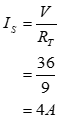
The total current supplied by the voltage source is the ratio of the voltage of voltage source and the total resistance seen by the voltage source and the same is given by:
The current entering the voltage source is equal to current supplied by voltage source. The current Ix is equal to current supplied by the voltage source that is 4A.
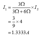
To calculate the current through 6Ω resistor, apply current division rule across the parallel combination of 6Ω and 3Ω:
Step by step
Solved in 2 steps with 7 images
![Blurred answer](/static/compass_v2/solution-images/blurred-answer.jpg)
![Introductory Circuit Analysis (13th Edition)](https://www.bartleby.com/isbn_cover_images/9780133923605/9780133923605_smallCoverImage.gif)
![Delmar's Standard Textbook Of Electricity](https://www.bartleby.com/isbn_cover_images/9781337900348/9781337900348_smallCoverImage.jpg)
![Programmable Logic Controllers](https://www.bartleby.com/isbn_cover_images/9780073373843/9780073373843_smallCoverImage.gif)
![Fundamentals of Electric Circuits](https://www.bartleby.com/isbn_cover_images/9780078028229/9780078028229_smallCoverImage.gif)
![Electric Circuits. (11th Edition)](https://www.bartleby.com/isbn_cover_images/9780134746968/9780134746968_smallCoverImage.gif)
![Engineering Electromagnetics](https://www.bartleby.com/isbn_cover_images/9780078028151/9780078028151_smallCoverImage.gif)