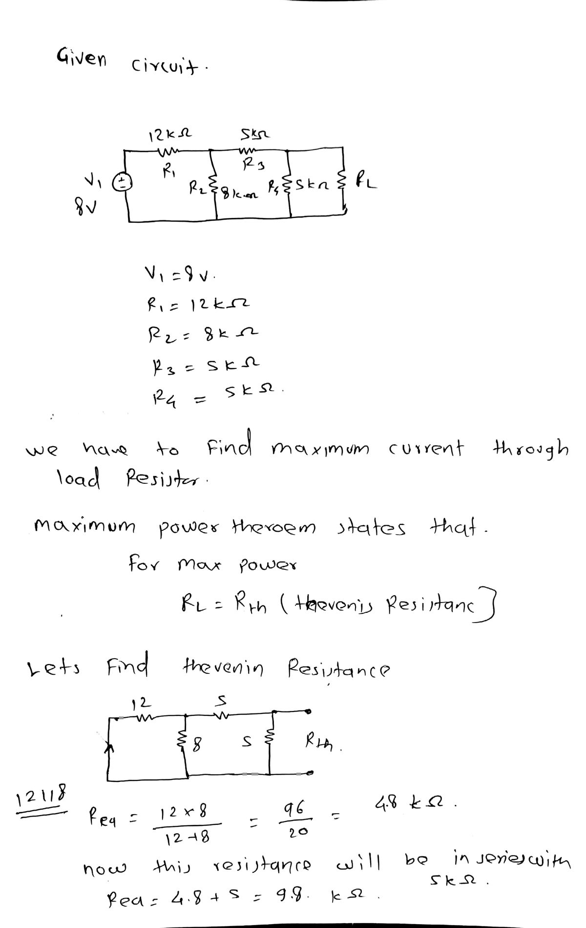
Find R, in the network above in order to achieve maximum power transfer. Take Vị = 8V, R1 = 12kN, R2 = 8KSN, R3 = 5kN and R4 = 5kN. RL = kN The open circuit voltage (with R, removed) is V. The power dissipated in the load resistor is Pr = mW.
Find R, in the network above in order to achieve maximum power transfer. Take Vị = 8V, R1 = 12kN, R2 = 8KSN, R3 = 5kN and R4 = 5kN. RL = kN The open circuit voltage (with R, removed) is V. The power dissipated in the load resistor is Pr = mW.

Introductory Circuit Analysis (13th Edition)
13th Edition
ISBN:9780133923605
Author:Robert L. Boylestad
Publisher:Robert L. Boylestad
Chapter1: Introduction
Section: Chapter Questions
Problem 1P: Visit your local library (at school or home) and describe the extent to which it provides literature...

Related questions
Question

Transcribed Image Text:**Find \( R_L \) in the network above in order to achieve maximum power transfer.**
Take \( V_1 = 8 \, \text{V} \), \( R_1 = 12 \, \text{k}\Omega \), \( R_2 = 8 \, \text{k}\Omega \), \( R_3 = 5 \, \text{k}\Omega \), and \( R_4 = 5 \, \text{k}\Omega \).
- \( R_L = \) \(\_\_\_\) \( \text{k}\Omega \)
- The open circuit voltage (with \( R_L \) removed) is \(\_\_\_\) V.
- The power dissipated in the load resistor is \( P_L = \) \(\_\_\_\) mW.
**Explanation of Diagrams**
In this exercise, you are tasked with finding the load resistance \( R_L \) that will allow for maximum power transfer in the given network. The diagram itself isn't visible here, but we can infer from the problem description that there is a network with a voltage source \( V_1 \) and several resistors \( R_1, R_2, R_3, \text{and } R_4 \).
To solve for \( R_L \), recall that maximum power transfer occurs when \( R_L \) is equal to the Thevenin resistance of the circuit not including \( R_L \). You may need to calculate the open circuit voltage with \( R_L \) removed to determine the Thevenin equivalent voltage. Then, use these values to calculate the power dissipated in the load resistor.

Transcribed Image Text:This diagram depicts an electrical circuit containing a voltage source \( V_1 \) and five resistors labeled \( R_1, R_2, R_3, R_4, \) and \( R_L \).
- The circuit begins with the voltage source \( V_1 \) on the left side.
- \( R_1 \) is connected in series with the voltage source.
- Two branches are connected in parallel:
- The first branch contains resistor \( R_2 \).
- The second branch contains resistors \( R_3 \) and \( R_4 \) in series.
- \( R_3 \) and \( R_4 \) are connected in series with each other.
- Following these, the circuit continues in series to the load resistor \( R_L \) on the right side.
- The circuit then closes back to the voltage source \( V_1 \).
This type of circuit is known as a combination circuit, featuring both series and parallel components. Understanding how to simplify and analyze such circuits is essential in electrical engineering and physics to determine total resistance, voltage, and current.
Expert Solution
Step 1

Step by step
Solved in 3 steps with 3 images

Recommended textbooks for you
Introductory Circuit Analysis (13th Edition)
Electrical Engineering
ISBN:
9780133923605
Author:
Robert L. Boylestad
Publisher:
PEARSON

Delmar's Standard Textbook Of Electricity
Electrical Engineering
ISBN:
9781337900348
Author:
Stephen L. Herman
Publisher:
Cengage Learning

Programmable Logic Controllers
Electrical Engineering
ISBN:
9780073373843
Author:
Frank D. Petruzella
Publisher:
McGraw-Hill Education
Introductory Circuit Analysis (13th Edition)
Electrical Engineering
ISBN:
9780133923605
Author:
Robert L. Boylestad
Publisher:
PEARSON
Delmar's Standard Textbook Of Electricity
Electrical Engineering
ISBN:
9781337900348
Author:
Stephen L. Herman
Publisher:
Cengage Learning
Programmable Logic Controllers
Electrical Engineering
ISBN:
9780073373843
Author:
Frank D. Petruzella
Publisher:
McGraw-Hill Education

Fundamentals of Electric Circuits
Electrical Engineering
ISBN:
9780078028229
Author:
Charles K Alexander, Matthew Sadiku
Publisher:
McGraw-Hill Education

Electric Circuits. (11th Edition)
Electrical Engineering
ISBN:
9780134746968
Author:
James W. Nilsson, Susan Riedel
Publisher:
PEARSON

Engineering Electromagnetics
Electrical Engineering
ISBN:
9780078028151
Author:
Hayt, William H. (william Hart), Jr, BUCK, John A.
Publisher:
Mcgraw-hill Education,