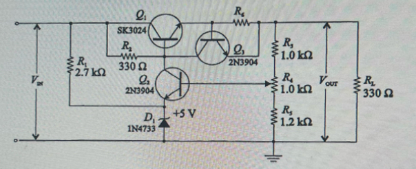
Figure 3 shows the series regulator from the experiment with the addition of current limiting Q3 and Re. Assume the current limit is set to 200 mA. Select a value for Re that will produce this limit. Show how the value is obtained.
Figure 3 shows the series regulator from the experiment with the addition of current limiting Q3 and Re. Assume the current limit is set to 200 mA. Select a value for Re that will produce this limit. Show how the value is obtained.

Introductory Circuit Analysis (13th Edition)
13th Edition
ISBN:9780133923605
Author:Robert L. Boylestad
Publisher:Robert L. Boylestad
Chapter1: Introduction
Section: Chapter Questions
Problem 1P: Visit your local library (at school or home) and describe the extent to which it provides literature...

Related questions
Question
How would the value be obtained?

Transcribed Image Text:### Series Regulator with Current Limiting
#### Description
1. **Figure 3** shows the series regulator from the experiment with the addition of current limiting transistors \( Q_3 \) and \( R_6 \). Assume the current limit is set to 200 mA. Select a value for \( R_6 \) that will produce this limit. Show how the value is obtained.
#### Circuit Explanation
The diagram presented is a series regulator circuit that includes a current limiting feature. The main components include:
- **Q1 (SK3024)** and **Q2/Q3 (2N3904)**, which are transistors involved in regulating current.
- **R1, R2, R3, R4,** and **R5 (1.0 kΩ)** resistors, which play roles in biasing and current limiting.
- **R6 (330 Ω)** is the resistor for which you need to determine a value to achieve the specified current limit of 200 mA.
- A Zener diode **(D1, 1N4733)** is used for voltage reference, maintaining a 5V output.
#### How to Determine \( R_6 \)
The task is to calculate the value for \( R_6 \) that will limit the current to 200 mA. To do this, you need to analyze the circuit and apply necessary calculations considering Ohm's Law and transistor operation principles.
#### Figure Caption
**Figure 3** – Series Regulator Circuit with Addition of Current Limiting
This configuration is essential for ensuring devices connected to the output are protected from excessive current, safeguarding against potential damage.
Expert Solution
Step 1: Requirement
The Amplifier circuit is given as
here we need to limit the current through resistance R6 i.e. maximum current flow through the R6 is 200mA.

Step by step
Solved in 3 steps with 4 images

Knowledge Booster


Learn more about
Need a deep-dive on the concept behind this application? Look no further. Learn more about this topic, electrical-engineering and related others by exploring similar questions and additional content below.Recommended textbooks for you
Introductory Circuit Analysis (13th Edition)
Electrical Engineering
ISBN:
9780133923605
Author:
Robert L. Boylestad
Publisher:
PEARSON

Delmar's Standard Textbook Of Electricity
Electrical Engineering
ISBN:
9781337900348
Author:
Stephen L. Herman
Publisher:
Cengage Learning

Programmable Logic Controllers
Electrical Engineering
ISBN:
9780073373843
Author:
Frank D. Petruzella
Publisher:
McGraw-Hill Education
Introductory Circuit Analysis (13th Edition)
Electrical Engineering
ISBN:
9780133923605
Author:
Robert L. Boylestad
Publisher:
PEARSON
Delmar's Standard Textbook Of Electricity
Electrical Engineering
ISBN:
9781337900348
Author:
Stephen L. Herman
Publisher:
Cengage Learning
Programmable Logic Controllers
Electrical Engineering
ISBN:
9780073373843
Author:
Frank D. Petruzella
Publisher:
McGraw-Hill Education

Fundamentals of Electric Circuits
Electrical Engineering
ISBN:
9780078028229
Author:
Charles K Alexander, Matthew Sadiku
Publisher:
McGraw-Hill Education

Electric Circuits. (11th Edition)
Electrical Engineering
ISBN:
9780134746968
Author:
James W. Nilsson, Susan Riedel
Publisher:
PEARSON

Engineering Electromagnetics
Electrical Engineering
ISBN:
9780078028151
Author:
Hayt, William H. (william Hart), Jr, BUCK, John A.
Publisher:
Mcgraw-hill Education,