F₁ = 100 H₂₁ Y ₂ = 2.5 KH₂ V for 4, = 1.976 (38.970 v in millivolts → V for f₁ = 2.7308 / 128.97° in V) L V₁ fort₁ = 3.2071 (4.37° V a for fyr 2(28.390 v R = 0.0691 (118.34° V for tr V₁ for t₁ = 7.006) (-0.21° V
Q: You have a 3 phase delta connected resistor network. The Line voltage is 240V and the line current…
A:
Q: An electric heater is designed to operate at 660W from a 120V source. If the source voltage drops to…
A: Power consumed P = 660 W.Initial voltage V = 120 V.Final voltage V = 80 V.
Q: The electric field of a plane wave propagating in a nonmagnetic material is given by 0 E=3.cos(2…
A:
Q: Determine the LT of {4sin (9t) x 2cos (6t)}
A: Find the laplace transform of the given equation
Q: If us (t) = 100√2 cos (1000t) V is the reference of the schematic in Fig. 1. vs(t) IT IR R₁ |10Ω IL…
A:
Q: The magnetic field of a wave propagating through a certain nonmagnetic material is given by H= (f) 0…
A:
Q: V1 500V 1.2kHz Total Impedance Trec = Tpolar = otal Current T(PK) = T(rms) R1 20092 units units…
A:
Q: 2. The three loads in Figure 2 are connected in parallel and the voltage across them is Vo 10020 V…
A: The three loads are connected in parallel as shown below,Here,the voltage,Vo = . The loads can be…
Q: Problem 4: Find the Norton equivalent with respect to the terminals ab for the circuit shown below.…
A: Given circuit:Asked to find the Norton equivalent circuit across the terminals a and b
Q: Given that A = 2 and B = 1, the following signal f(t) can be expressed as: -2A -A 3B 2B B -B -2B…
A: Given that A=2 and B= 1, the following signal f(t) can be expressed as:A waveform has discontinuity…
Q: Problem 5: Find the equivalent resistance of the following networks as viewed from their ports.…
A: The given circuits area.b.c.We need to find the equivalent resistance for the given circuits.
Q: You count 8 cycles across 8.3 time divisions on an oscilloscope screen. The time sweep is set to…
A: Number of cycles, The time of each division is 2.5 ms,The peak voltage,
Q: If it is assumed that all the sources in the circuit of Fig. 7.70 have been con- nected and…
A: Given a circuit, we need to determine: using superposition theorem. Assuming all sources are…
Q: P 11.3-1 An RLC circuit is shown in Figure P 11.3-1. Find the instantaneous power delivered to the…
A: Circuit:Sorce current, Angular frequency,
Q: If R = 11 ft and superposition is used to compute the current I, what are the individual solutions…
A: The circuit diagram,
Q: g) _x[n] = 2sin (²2πn+7)u[n] h) x[n] = 0.4"sin (2nn) u[n]
A: Given Data:The discrete-time signals,g. h. To Find:Z-transform,Pole-zero plotROC
Q: What is the value of 12 in the network shown below? BY ㅏ 4V + 10, 12 16 V
A: Here,
Q: E = 100 V < 0° Μ 3 Ω +₁₁ 4Ω Xc² 2 ΖΩ
A: calculation of Thevenin equivalent of circuit:Let us redraw circuit in impedance domain:
Q: 3.68 A digital circuit is required to display a digital signal on a bar-graph LED, similar to a…
A: As per the given information, we need to:a) write the truth table with D1 and D0 as inputs and Y1,…
Q: Problem 5-4. Find the value of the load resistance R₁ in figure P5.16 which will dissipate maximum…
A: The given circuit isWe need to find the value of the load resistance so that maximum power will…
Q: 4.156. Find the on-resistance of the JFET in Fig. P4.156 if Ipss = 1 mA and Vp = -5 V. Repeat for…
A:
Q: The Current Temple Puzzle Scenario: While exploring an ancient temple, you come across a chamber…
A: As per the given information,we can draw the circuit as, here we have considered the LED which has…
Q: ACD' + C'D + AB' + ABCD 1. Obtain the KMAP to get minterms and maxterms 2. What are the Minterms?…
A:
Q: Find the Norton equivalent circuit
A: In this question, we need to determine the Norton equivalent circuit across the terminals a and b.
Q: A BD D Da: ▷ What is the Boolean expression for this circuit? (AⓇB) (C+B) = X (A+B) + (C•D) = X ● (A…
A: Given:a logic circuit, we need to find:the logic expression for the output X.
Q: B) If a current signal Is(t) = 10 cos (10t) A is applied to the circuit, determine the value of the…
A: In the given questions we need to calculate the apparent power of the given circuit.
Q: 1. If an amplifier has 6 dB of gain, how much is the power increased? How much is the voltage…
A:
Q: Show that ZT=3.38+j1.08 Ω.
A:
Q: Ⓒ3 Consider this primitive shunt regulator If V₂ = 12 V, find Iz and Vo for ISV + 501 INT Re Vo 13.1…
A: Forr the given shunt regulator Guess and check to confirm wheter the zener diode is ON or not.
Q: 5-5. Repeat problem P5-4 if VR = 15 227.4° V and Vc = 5 Z-62.6° V.
A: Given circuit:Write VR and VC in rectangular formDetermine voltage V in both rectangular and polar…
Q: Find the phase relationship between the following waveforms: v = -4 cos(wt + 90°) i=-2 sin(wt + 10°)
A: For the given voltage and current values in the time domain, the phase relationship between them…
Q: What role does the RC time constant play in a filter circuit ?. In designing of a filter following a…
A: The above question is based on the role of RC time constant in filters.
Q: 12ΚΩ 309 -15V 6 Vpk 1kHz 0 ε 15V -15V
A: Given circuit is , a)…
Q: XL + E₁ = 20 V Z 0° 3 Ω L'with E2 shorted & I opened= IL"with E1 shorted & I opened= IL"with E1…
A:
Q: a) When an antenna is operating at its resonant point, what is the nature of its feedpoint…
A: "Since you have posted a question with multiple sub parts, we will provide the solution only to the…
Q: 3.1.48 Use nodal analysis to determine the node voltages defined in the circuit in Fig. P3.1.48. 10…
A:
Q: Solve the circuit unknowns in the picture below
A: In the given circuit the value of the unknown voltage and current needs to be calculated based on…
Q: Vs1 Is V₂ +51 m 12 11 Vs2 + R2 R₁ V3 Z1 = (enter an integer value,...-2,-1,0,1,2,...) 2₂ = (enter an…
A: Given a network, with, And some equatons, To find:The values of variables x1, x2, x3, x4 and x5 in…
Q: 5-3-22 Find 1, in the network in Eig.P5.3.22 using Thévenin's theorem. τον 1 ΚΩ ww 12 mA ΣΖΚΩ ΣΚΟΥ…
A: The question is about finding the current I0 using thevenin's theorem.
Q: 3. (20 points) Consider the cascade connection of the two amplifiers shown in Figure 3. + Vil R₁ 2ΜΩ…
A:
Q: 2. Two signals, x,(7) and x₂(1), are defined as follows, 0 = {6 x₂(t)= 3 1 -2.5 x3 (1)= and are…
A:
Q: Problem 2: Given the following circuit with an ideal op-amp, 8 V + 10 ΚΩ + Vin 4 ΚΩ M 1 ΚΩ M 1 ΚΩ 20…
A: In this question, we need to determine the range of voltage for linear operation and also…
Q: the circuit shown in (Figure 1). Suppose that R = 12. Figure 12 02 www 240 V 1 t=0 R 402 www 72 mH…
A: Given Data:A DC resistive circuit with,Input voltage To Find:The percentage of the initial energy…
Q: Solve using the mesh-current method. then find Find using the node-voltage method. V₂ Solve using…
A: For the given circuits the value of the unknown voltages needs to be calculated by using the…
Q: Question: Two parallel conductors, each of 0.6 m length, separated by 6 mm carry equal currents of…
A: Here,parallel conductors, each of length, l = 0.6 mseparated by distance, d = 6 mmcarrying equal…
Q: Calculate the time, in milliseconds, it takes to deliver 7.2 mJ to the black box.
A: Given:a circuit, with for t>0, . To find:the time, in milliseconds, it takes to deliver 7.2 mJ to…
Q: 1. If an amplifier has 6 dB of gain, how much is the power increased? How much is the voltage…
A:
Q: VI. Review Questions Solve the following R₁ 10 Q 114 1. R₁ www 14 Q2 20 Ω www R₂ Va Rs 60 www 20 V…
A:
Q: For the number 1 question, you have to find the thevenin equivalent resistance at the load terminals…
A: In the given questions we need to calculate the thevenin equivalent resistance and maximum power…
Q: 1. 2ov 152 খম 12 R 552 30 V
A: NOTE: As per our company guidelines we are supposed to answer only one question at a time.So we…
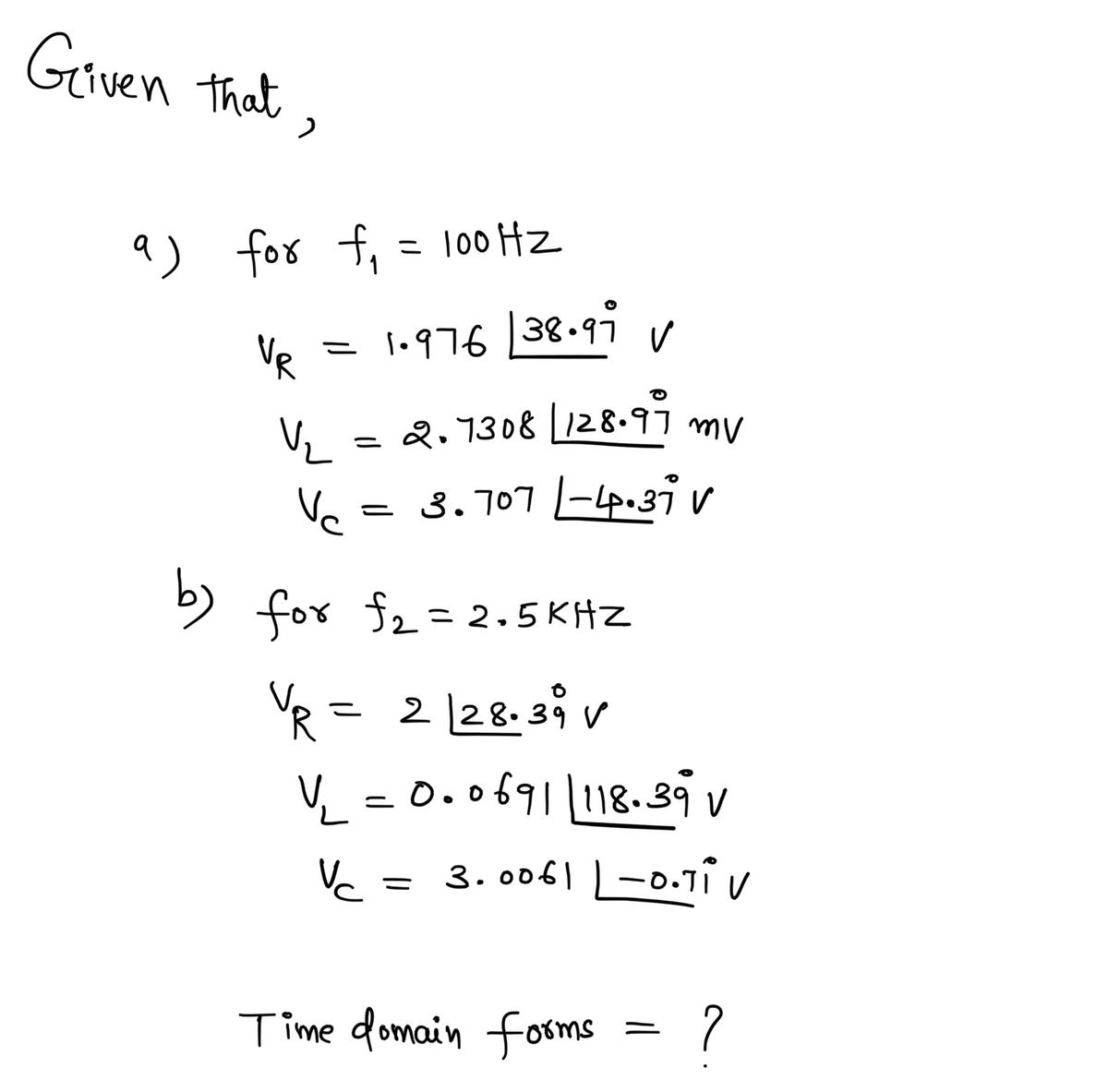
Please convert these values into time domain forms, not the rectangular coordinates, ie v(t) = Acos(wt + theta) form
Step by step
Solved in 3 steps with 3 images
- A 15-F AC capacitor is connected in series with a 50 resistor. The capacitor has a voltage rating of 600 WVDC. The capacitor and resistor are connected to a 480-V, 60-Hz circuit. Is the voltage rating of the capacitor sufficient for this connection?You find that a 25-F capacitor connected to 480 VAC is defective. The storeroom has no capacitors with a 480-VAC rating. However, you find two capacitors rated at 50 F and 370 VAC. Can these two capacitors be connected in such a manner that they can replace the defective capacitor? If yes, explain how they are connected and why the capacitors will not be damaged by the lower voltage rating. If no, explain why they cannot be used without damaging the capacitor.0 1 2 Previous Next Iculate Score 0610908 - Introduction to Electrical Phase 1 7 of 20 Which DMM measurement would you expect based upon the red and black leads in this image? ⒸOV 2.5 V Ⓒ 6V 12 V 20 Q Search LDC ASUS T
- 2. Convert the following values from microfarads to picofarads: a. 0.1 μF b. 0.0025 μFIdentify which measurement this oscilloscope time difference reading is useful for. Oscilloscope-XSC1 Time 250.000 us 1.261 ms Channel_A 169.064 V 168.513 V -550. 584 mV Channel_B 89. 282 V 95.005 V 5.722 V Reverse T2-T1 1.011 ms Save Ext. trigger Timebase Scale: 200 us/Div : Scale: 100 V/Div X pos. (Div): 0 Channel A Channel B Scale: 100 V/Div Y pos. (Div): 0 Trigger Edge: F Level: 0 A B Ext Y pos. (Div): 0 V Y/T Add B/A A/B AC DC AC DC Single Normal O period O none of the above O phase shiftPower factor 90 to 100% 88 to <90% 85 to <88% 80 to <85% 75 to < 80% 70 to < 75% 65 to < 70% 60 to <65% 55 to <60% 50 to <55% Less than 50% Surcharge None 2% 4% 9% 16% 24% 34% 44% 57% 72% 80% Use the table given for the following. A house with inductive loads has an avg consumption of 40kW and 26kVAR is supplied 230 Vrms source. We want to make the surcharge 0% by adding a capacitor. a. What is the smallest kVar of the capacitor that would reduce the surcharge to 0%?
- Circuits 1 HW 6 Q9QUESTION 3 An inductor, a capacitor, and a resistor are connected in parallel with a function generator. The inductor draws 100mA RMS, the capacitor draws 150mA RMS, and the resistor draws 200mA RMS. Find the magnitude of the total current. O 450mA RMS O 544mA RMS O 352mA RMS O 206mA RMSRegarding behavior of inductors and capacitors in circuits, select the correctstatement -a) Voltage leads current in a capacitive circuit,b) Current leads voltage by 180 degrees in a pure capacitor,c) Voltage leads current by 45 degrees in a pure inductor,d) Current leads voltage in an inductive circuit,e) Current lags voltage in a pure capacitor by 90 degrees,f) Current lags voltage by 90 degrees in a pure inductor
- 10 V sine 90 kHz 1 kQ C1 1 nF 2. Using a Square function with 90,000 Hz in your function-generator, a 1000-ohm resistor, and a 1 nano-Farad capacitor, determine the charging time for the capacitor. Show your calculations and show the charging-discharge curve with an oscilloscope in TINKERCAD.The peak to peak distance of a sinusoidal waveform displayed on a C.R.O. screen is 9 cm and the 'volts/cm' switch is on 25 V/cm. The peak voltage is given by O 2.78 V O 159.07 V O 112.50 V O 225.00 VQ1(a) Analyze the polar form of this waveform in Figure Q1(a). 60 V 310⁰ Figure Q1(a)