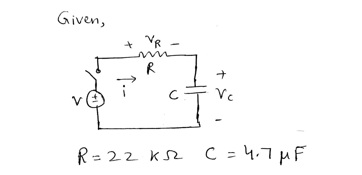
Extra problem 1: For the RC circuit shown in Figure 8.15 of Bolton's textbook (page 197), write the first- order differential equation with a numerical value for the time-constant t = RC for the parameter values F = 22 k2 and C= 4.7 uF. main
Extra problem 1: For the RC circuit shown in Figure 8.15 of Bolton's textbook (page 197), write the first- order differential equation with a numerical value for the time-constant t = RC for the parameter values F = 22 k2 and C= 4.7 uF. main

Introductory Circuit Analysis (13th Edition)
13th Edition
ISBN:9780133923605
Author:Robert L. Boylestad
Publisher:Robert L. Boylestad
Chapter1: Introduction
Section: Chapter Questions
Problem 1P: Visit your local library (at school or home) and describe the extent to which it provides literature...

Related questions
Question
Extra Problem #1

Transcribed Image Text:1
T
from Bateso
Chapter 8, Problems: 4, 6 (page 207)
Chapter 10, Problems: 11, 13 (page 254)
Extra problem 1: For the RC circuit shown in Figure 8.15 of Bolton's textbook (page 197), write the first-
order differential equation with a numerical value for the time-constant T = RC for the parameter values R
= 22 k2 and C= 4.7 µF.
5
Extra problem 2: Determine the frequency-domain function F(s) for each of the following time-domain
functions f(t) using Laplace Transforms.
a. f(t)=7.8
b. f(t)=3.2 cos 1000t
c. f(t)= 120 sin 25t
d. f(t)= 18t
e. f(t)=16e&
1.
O Search
T
f(t)=85
A
d²x +5=
6
di² dt
dx(0)
Y
dx
&
4-
7
*
8
U T
(
O
f10
O
2
O
P
A
S
prt so

Transcribed Image Text:▬▬
8.3 DYNAMIC SYSTEMS
EXAMPLE
Develop a model for the electrical system described by the circuit shown in Figure 8.15. The input is the voltage v
when the switch is closed and the output is the voltage vc across the capacitor.
Using Kirchhoff's voltage law gives
and, since VR = Ri and i=C(dvc/dt) we obtain the equation:
V=UR + VC
and so
v=RC
FIGURE 8.15 Electrical system with resistance and capacitance.
The relationship between an input v and the output vc is a first-order differential equation. The term first order is used
because it includes as its highest derivative dv/dt.
O Search
duc
dt
VR
+ oc
R
EXAMPLE
Develop a model for the circuit shown in Figure 8.16 when we have an input voltage v when the switch is closed and
take an output as the voltage vc across the capacitor.
Applying Kirchhoff's voltage law gives
TVC
V = VR + V₁ + VC
di
v-Ri+Ldt
Since i = C(dvc/dt), then di/dt = C(d²vc/df) and thus we can write
ducd²uc
+ UC
197
D
1668
Expert Solution
Step 1

Step by step
Solved in 2 steps with 2 images

Recommended textbooks for you
Introductory Circuit Analysis (13th Edition)
Electrical Engineering
ISBN:
9780133923605
Author:
Robert L. Boylestad
Publisher:
PEARSON

Delmar's Standard Textbook Of Electricity
Electrical Engineering
ISBN:
9781337900348
Author:
Stephen L. Herman
Publisher:
Cengage Learning

Programmable Logic Controllers
Electrical Engineering
ISBN:
9780073373843
Author:
Frank D. Petruzella
Publisher:
McGraw-Hill Education
Introductory Circuit Analysis (13th Edition)
Electrical Engineering
ISBN:
9780133923605
Author:
Robert L. Boylestad
Publisher:
PEARSON
Delmar's Standard Textbook Of Electricity
Electrical Engineering
ISBN:
9781337900348
Author:
Stephen L. Herman
Publisher:
Cengage Learning
Programmable Logic Controllers
Electrical Engineering
ISBN:
9780073373843
Author:
Frank D. Petruzella
Publisher:
McGraw-Hill Education

Fundamentals of Electric Circuits
Electrical Engineering
ISBN:
9780078028229
Author:
Charles K Alexander, Matthew Sadiku
Publisher:
McGraw-Hill Education

Electric Circuits. (11th Edition)
Electrical Engineering
ISBN:
9780134746968
Author:
James W. Nilsson, Susan Riedel
Publisher:
PEARSON

Engineering Electromagnetics
Electrical Engineering
ISBN:
9780078028151
Author:
Hayt, William H. (william Hart), Jr, BUCK, John A.
Publisher:
Mcgraw-hill Education,