Example 23: Determine RTh for the circuit shown in Figure 54 using the circuit voltage, short circuit current method and the external source method. Also determine VTh. 2 kN a Voc 5 V 3 v 20 i v $25 N ground
Example 23: Determine RTh for the circuit shown in Figure 54 using the circuit voltage, short circuit current method and the external source method. Also determine VTh. 2 kN a Voc 5 V 3 v 20 i v $25 N ground

Introductory Circuit Analysis (13th Edition)
13th Edition
ISBN:9780133923605
Author:Robert L. Boylestad
Publisher:Robert L. Boylestad
Chapter1: Introduction
Section: Chapter Questions
Problem 1P: Visit your local library (at school or home) and describe the extent to which it provides literature...

Related questions
Question
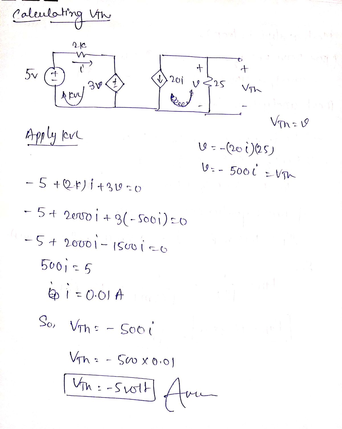
I need help finding VTh and RTh in the following circuit.

Transcribed Image Text:**Example 23:**
Determine \( R_{Th} \) for the circuit shown in Figure 54 using the circuit voltage, short circuit current method, and the external source method. Also determine \( V_{Th} \).
**Circuit Description:**
- **Voltage Source:** There is a 5V voltage source on the left.
- **Components:**
- A 2 kΩ resistor is connected to the voltage source.
- The circuit contains a controlled current source labeled as \( 20i \).
- A 25Ω resistor is in parallel with the controlled source.
- **Nodes and Connections:**
- There are two main nodes labeled 'a' and 'b'.
- The ground is connected between the 3V voltage source and the controlled current source.
- **Voltage Measurements:**
- \( V_1 \) is labeled across the 25Ω resistor.
- \( V_{oc} \) represents the open circuit voltage between nodes 'a' and 'b'.
The diagram shows a typical circuit schematic used for calculating Thevenin’s equivalent resistance and voltage. The calculation involves:
1. **Using Circuit Voltage:** Analyzing the voltage across components.
2. **Short Circuit Current Method:** Calculating the current through a short across 'a' and 'b'.
3. **External Source Method:** Adding an external source to find equivalent resistance.
These methods help determine \( R_{Th} \) and \( V_{Th} \), essential for simplifying complex linear circuits into a single voltage source and series resistance.
Expert Solution
Step 1

Step by step
Solved in 2 steps with 2 images

Knowledge Booster


Learn more about
Need a deep-dive on the concept behind this application? Look no further. Learn more about this topic, electrical-engineering and related others by exploring similar questions and additional content below.Recommended textbooks for you
Introductory Circuit Analysis (13th Edition)
Electrical Engineering
ISBN:
9780133923605
Author:
Robert L. Boylestad
Publisher:
PEARSON

Delmar's Standard Textbook Of Electricity
Electrical Engineering
ISBN:
9781337900348
Author:
Stephen L. Herman
Publisher:
Cengage Learning

Programmable Logic Controllers
Electrical Engineering
ISBN:
9780073373843
Author:
Frank D. Petruzella
Publisher:
McGraw-Hill Education
Introductory Circuit Analysis (13th Edition)
Electrical Engineering
ISBN:
9780133923605
Author:
Robert L. Boylestad
Publisher:
PEARSON
Delmar's Standard Textbook Of Electricity
Electrical Engineering
ISBN:
9781337900348
Author:
Stephen L. Herman
Publisher:
Cengage Learning
Programmable Logic Controllers
Electrical Engineering
ISBN:
9780073373843
Author:
Frank D. Petruzella
Publisher:
McGraw-Hill Education

Fundamentals of Electric Circuits
Electrical Engineering
ISBN:
9780078028229
Author:
Charles K Alexander, Matthew Sadiku
Publisher:
McGraw-Hill Education

Electric Circuits. (11th Edition)
Electrical Engineering
ISBN:
9780134746968
Author:
James W. Nilsson, Susan Riedel
Publisher:
PEARSON

Engineering Electromagnetics
Electrical Engineering
ISBN:
9780078028151
Author:
Hayt, William H. (william Hart), Jr, BUCK, John A.
Publisher:
Mcgraw-hill Education,