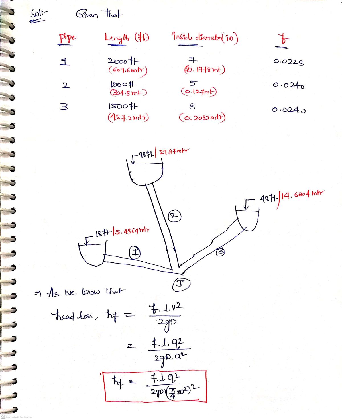
EXAMPLE 10.4. The three pipes in figure are cast iron with characteristics as shown in table. The three pipes are interconnected at junction J. Water temperature is 68°F. Calculate the flow in each pipe. 98 ft 48 ft 18 ft Length (ft) 2000 Pipe Inside diameter (in) f 1 7 0.0225 2 1000 0.0240 3 1500 8 0.0240
EXAMPLE 10.4. The three pipes in figure are cast iron with characteristics as shown in table. The three pipes are interconnected at junction J. Water temperature is 68°F. Calculate the flow in each pipe. 98 ft 48 ft 18 ft Length (ft) 2000 Pipe Inside diameter (in) f 1 7 0.0225 2 1000 0.0240 3 1500 8 0.0240

Chapter2: Loads On Structures
Section: Chapter Questions
Problem 1P

Related questions
Question
Someone can help me with this one please

Transcribed Image Text:**Example 10.4:**
The diagram illustrates a system with three interconnected cast iron pipes at junction J. The table provides specific characteristics of each pipe. The objective is to calculate the flow in each pipe given that the water temperature is 68°F.
**Diagram Explanation:**
- The system consists of three pipes labeled 1, 2, and 3.
- Each pipe connects to a node, indicated with different height levels where the water enters:
- Pipe 1 with an elevation of 18 ft.
- Pipe 2 with an elevation of 98 ft.
- Pipe 3 with an elevation of 48 ft.
- All pipes merge at junction J.
**Table Description:**
| Pipe | Length (ft) | Inside diameter (in) | f (friction factor) |
|------|-------------|----------------------|-------------------|
| 1 | 2000 | 7 | 0.0225 |
| 2 | 1000 | 5 | 0.0240 |
| 3 | 1500 | 8 | 0.0240 |
- **Pipe 1** is 2000 feet long with an inside diameter of 7 inches and a friction factor of 0.0225.
- **Pipe 2** is 1000 feet long with an inside diameter of 5 inches and a friction factor of 0.0240.
- **Pipe 3** is 1500 feet long with an inside diameter of 8 inches and a friction factor of 0.0240.
To calculate the flow in each pipe, use the given parameters (length, diameter, elevation, and friction factor) and apply relevant hydraulics equations.
Expert Solution
Step 1

Step by step
Solved in 2 steps with 2 images

Knowledge Booster


Learn more about
Need a deep-dive on the concept behind this application? Look no further. Learn more about this topic, civil-engineering and related others by exploring similar questions and additional content below.Recommended textbooks for you

Structural Analysis (10th Edition)
Civil Engineering
ISBN:
9780134610672
Author:
Russell C. Hibbeler
Publisher:
PEARSON

Principles of Foundation Engineering (MindTap Cou…
Civil Engineering
ISBN:
9781337705028
Author:
Braja M. Das, Nagaratnam Sivakugan
Publisher:
Cengage Learning
Structural Analysis (10th Edition)
Civil Engineering
ISBN:
9780134610672
Author:
Russell C. Hibbeler
Publisher:
PEARSON
Principles of Foundation Engineering (MindTap Cou…
Civil Engineering
ISBN:
9781337705028
Author:
Braja M. Das, Nagaratnam Sivakugan
Publisher:
Cengage Learning

Fundamentals of Structural Analysis
Civil Engineering
ISBN:
9780073398006
Author:
Kenneth M. Leet Emeritus, Chia-Ming Uang, Joel Lanning
Publisher:
McGraw-Hill Education


Traffic and Highway Engineering
Civil Engineering
ISBN:
9781305156241
Author:
Garber, Nicholas J.
Publisher:
Cengage Learning