### Circuit Diagram Analysis The image depicts a complex resistive circuit on a grid background. The circuit consists of multiple resistors connected in series and parallel configurations. Here's a detailed breakdown of the circuit components and their connections: 1. **Resistors:** - **12 Ω Resistor:** Connected in series from the left vertical branch to the center node. - **4 Ω Resistor:** Connected horizontally from the top center node to the rightmost node. - **24 Ω Resistor:** Connected vertically from the top right node to the bottom right node. - **8 Ω Resistor:** Positioned horizontally on the rightmost side, in series with the 24 Ω resistor. - **5 Ω Resistor:** Connected towards the bottom left. - **30 Ω Resistor:** Connected horizontally from the center to the bottom right node. - **Resistor R:** Placed diagonally from the upper center node to the bottom right node. 2. **Input Resistance (Rin):** - The circuit has an input resistance, \( R_{\text{in}} \), given as \( 9 \, \Omega \). 3. **Nodes and Pathways:** - The circuit has several nodes where resistors are interconnected, forming multiple loops and pathways for current flow. ### Problem Statement The task is to determine the value of the unknown resistor \( R \). ### Analysis Viewpoint To find the value of the resistor \( R \), apply principles such as series-parallel resistance calculations and perhaps use methods like mesh analysis or the node-voltage method to solve for \( R \), ensuring the total equivalent resistance matches the given \( R_{\text{in}} = 9 \, \Omega \). ### Conclusion By combining knowledge of electrical circuits and resistive networks, one can determine the value of the variable resistor \( R \) tailored to achieve the specified input resistance for the circuit.
### Circuit Diagram Analysis The image depicts a complex resistive circuit on a grid background. The circuit consists of multiple resistors connected in series and parallel configurations. Here's a detailed breakdown of the circuit components and their connections: 1. **Resistors:** - **12 Ω Resistor:** Connected in series from the left vertical branch to the center node. - **4 Ω Resistor:** Connected horizontally from the top center node to the rightmost node. - **24 Ω Resistor:** Connected vertically from the top right node to the bottom right node. - **8 Ω Resistor:** Positioned horizontally on the rightmost side, in series with the 24 Ω resistor. - **5 Ω Resistor:** Connected towards the bottom left. - **30 Ω Resistor:** Connected horizontally from the center to the bottom right node. - **Resistor R:** Placed diagonally from the upper center node to the bottom right node. 2. **Input Resistance (Rin):** - The circuit has an input resistance, \( R_{\text{in}} \), given as \( 9 \, \Omega \). 3. **Nodes and Pathways:** - The circuit has several nodes where resistors are interconnected, forming multiple loops and pathways for current flow. ### Problem Statement The task is to determine the value of the unknown resistor \( R \). ### Analysis Viewpoint To find the value of the resistor \( R \), apply principles such as series-parallel resistance calculations and perhaps use methods like mesh analysis or the node-voltage method to solve for \( R \), ensuring the total equivalent resistance matches the given \( R_{\text{in}} = 9 \, \Omega \). ### Conclusion By combining knowledge of electrical circuits and resistive networks, one can determine the value of the variable resistor \( R \) tailored to achieve the specified input resistance for the circuit.

Introductory Circuit Analysis (13th Edition)
13th Edition
ISBN:9780133923605
Author:Robert L. Boylestad
Publisher:Robert L. Boylestad
Chapter1: Introduction
Section: Chapter Questions
Problem 1P: Visit your local library (at school or home) and describe the extent to which it provides literature...

Related questions
Question

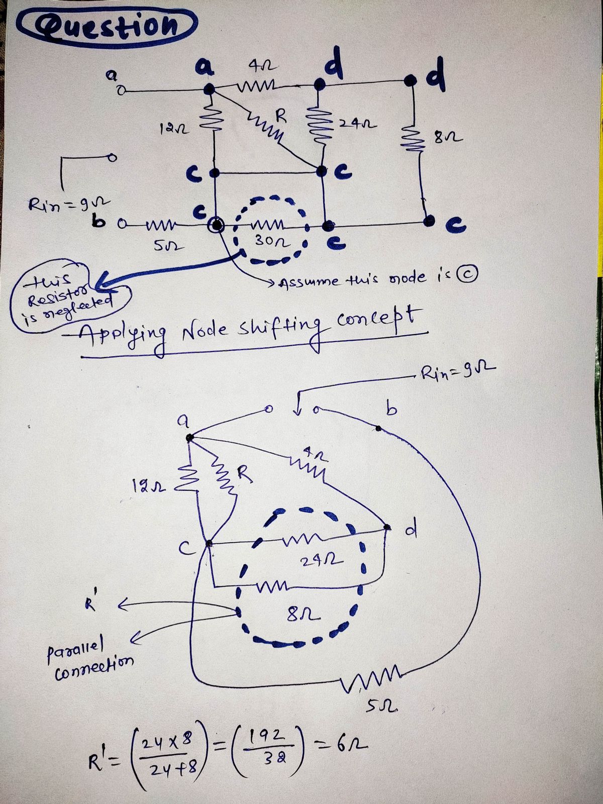
Transcribed Image Text:### Circuit Diagram Analysis
The image depicts a complex resistive circuit on a grid background. The circuit consists of multiple resistors connected in series and parallel configurations. Here's a detailed breakdown of the circuit components and their connections:
1. **Resistors:**
- **12 Ω Resistor:** Connected in series from the left vertical branch to the center node.
- **4 Ω Resistor:** Connected horizontally from the top center node to the rightmost node.
- **24 Ω Resistor:** Connected vertically from the top right node to the bottom right node.
- **8 Ω Resistor:** Positioned horizontally on the rightmost side, in series with the 24 Ω resistor.
- **5 Ω Resistor:** Connected towards the bottom left.
- **30 Ω Resistor:** Connected horizontally from the center to the bottom right node.
- **Resistor R:** Placed diagonally from the upper center node to the bottom right node.
2. **Input Resistance (Rin):**
- The circuit has an input resistance, \( R_{\text{in}} \), given as \( 9 \, \Omega \).
3. **Nodes and Pathways:**
- The circuit has several nodes where resistors are interconnected, forming multiple loops and pathways for current flow.
### Problem Statement
The task is to determine the value of the unknown resistor \( R \).
### Analysis Viewpoint
To find the value of the resistor \( R \), apply principles such as series-parallel resistance calculations and perhaps use methods like mesh analysis or the node-voltage method to solve for \( R \), ensuring the total equivalent resistance matches the given \( R_{\text{in}} = 9 \, \Omega \).
### Conclusion
By combining knowledge of electrical circuits and resistive networks, one can determine the value of the variable resistor \( R \) tailored to achieve the specified input resistance for the circuit.
Expert Solution
Step 1

Step by step
Solved in 4 steps with 4 images

Recommended textbooks for you
Introductory Circuit Analysis (13th Edition)
Electrical Engineering
ISBN:
9780133923605
Author:
Robert L. Boylestad
Publisher:
PEARSON

Delmar's Standard Textbook Of Electricity
Electrical Engineering
ISBN:
9781337900348
Author:
Stephen L. Herman
Publisher:
Cengage Learning

Programmable Logic Controllers
Electrical Engineering
ISBN:
9780073373843
Author:
Frank D. Petruzella
Publisher:
McGraw-Hill Education
Introductory Circuit Analysis (13th Edition)
Electrical Engineering
ISBN:
9780133923605
Author:
Robert L. Boylestad
Publisher:
PEARSON
Delmar's Standard Textbook Of Electricity
Electrical Engineering
ISBN:
9781337900348
Author:
Stephen L. Herman
Publisher:
Cengage Learning
Programmable Logic Controllers
Electrical Engineering
ISBN:
9780073373843
Author:
Frank D. Petruzella
Publisher:
McGraw-Hill Education

Fundamentals of Electric Circuits
Electrical Engineering
ISBN:
9780078028229
Author:
Charles K Alexander, Matthew Sadiku
Publisher:
McGraw-Hill Education

Electric Circuits. (11th Edition)
Electrical Engineering
ISBN:
9780134746968
Author:
James W. Nilsson, Susan Riedel
Publisher:
PEARSON

Engineering Electromagnetics
Electrical Engineering
ISBN:
9780078028151
Author:
Hayt, William H. (william Hart), Jr, BUCK, John A.
Publisher:
Mcgraw-hill Education,