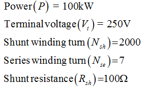
Each pole of a 100 kW, 250 V flat-compound generator has a shunt field of 2000 turns and
Each pole of a 100 kW, 250 V flat-compound generator has a shunt field of 2000 turns and

Computer Networking: A Top-Down Approach (7th Edition)
7th Edition
ISBN:9780133594140
Author:James Kurose, Keith Ross
Publisher:James Kurose, Keith Ross
Chapter1: Computer Networks And The Internet
Section: Chapter Questions
Problem R1RQ: What is the difference between a host and an end system? List several different types of end...

Related questions
Question
11 letters a and b.
![a of 7 If the total shunt-
when the at rated voltage
field is 100 N, mmf
exciting to 120 Va
Fig. 18b the saturation
curve of a dc generator
DIRECT-CURRENT GENERATORS
92
Questions and Problems m6
a. at no-load
b. at full-load
Practical level
Sketch the main components of a dc
1.
generator.
2 Why are the brushes of a dc machine always
placed at the neutral points?d lo ioqbim
Describe the construction of a commutator.
12
curve of a separately excited dc generator
when it revolves at 1500 r/min. Calculata
3
How is the induced voltage of a separately
excited dc generator affected if
a. the speed increases?
b. the exciting current is reduced?
1330 r/min.
13 Referring to Fig. 10, the induced voltage :,
coil D is momentarily 18 V, in the position
shown. Calculate the voltages induced in
coils A, B, and C at the same instant.
4
450
5.
generator?
How do we adjust the voltage of a shunt
14
Referring to Fig. 11b, calculate the voltage
6.
The terminal voltage of a shunt generator
decreases with increasing load. Explain.
induced in coil A when the armature has
ro-
tated by 90°; by 120°.
Explain why the output voltage of an over-
compound generator increases as the load h
increases.
Brush x is positive with respect to brush y in
15
Fig. 11b. Show the polarity of each of the 12
coils. Does the polarity reverse when a coil
8.
pound, and differential compound generators
Explain the difference between shunt, com-
turns through 180°?
a. as to construction
b. as to electrical properties
The generator of Fig. 38 revolves at
960 r/min and the flux per pole is 20 mWb.
Calculate the no-load armature voltage if
Intermediate level
each armature coil has 6 turns.
Com
9 A separate excited dc generator turning at
1400 r/min produces an induced voltage of
127 V. The armature resistance is 2 and m
shos the machine delivers a current of 12 A. T
17
a. How many brush sets are needed for the
generator in Fig. 38?
b. If the machine delivers a total load
(a)
flowing in each armature coil.
current of 1800 A, calculate the current
Calculate
gomta. the terminal voltage [V]
b. the heat dissipated in the armature [W]
lo no C. the braking torque exerted by the
dene
Advanced level
The voltage between brushes x and y is
240 V in the generator shown in Fig. 38.
Why can we say that the voltage between
armature [N m]
o viluto i
10.
no-load voltage of 115 V. What happens if
a. the speed is increased by 20 percent?h
b. the direction of rotation is reversed?
c. the exciting current is increased by
10 percent?
d. the polarity of the field is reversed?
11 Each pole of a 100 kW, 250 V flat-compound
A separately excited dc generator produces a
Referring to Fig. 10, determine the polarily
clockwise.
20
a. In Fig. 38 determine the polarity of P
generator has a shunt field of 2000 turns and
ECUGUI
knowing that the armature is turning
clockwise.](/v2/_next/image?url=https%3A%2F%2Fcontent.bartleby.com%2Fqna-images%2Fquestion%2F585e4a80-646c-4418-ada9-cb992a2ce44b%2F1aa11a1f-f4fb-46c0-8430-762e74e1e1ed%2F9ws83d.jpeg&w=3840&q=75)
Transcribed Image Text:a of 7 If the total shunt-
when the at rated voltage
field is 100 N, mmf
exciting to 120 Va
Fig. 18b the saturation
curve of a dc generator
DIRECT-CURRENT GENERATORS
92
Questions and Problems m6
a. at no-load
b. at full-load
Practical level
Sketch the main components of a dc
1.
generator.
2 Why are the brushes of a dc machine always
placed at the neutral points?d lo ioqbim
Describe the construction of a commutator.
12
curve of a separately excited dc generator
when it revolves at 1500 r/min. Calculata
3
How is the induced voltage of a separately
excited dc generator affected if
a. the speed increases?
b. the exciting current is reduced?
1330 r/min.
13 Referring to Fig. 10, the induced voltage :,
coil D is momentarily 18 V, in the position
shown. Calculate the voltages induced in
coils A, B, and C at the same instant.
4
450
5.
generator?
How do we adjust the voltage of a shunt
14
Referring to Fig. 11b, calculate the voltage
6.
The terminal voltage of a shunt generator
decreases with increasing load. Explain.
induced in coil A when the armature has
ro-
tated by 90°; by 120°.
Explain why the output voltage of an over-
compound generator increases as the load h
increases.
Brush x is positive with respect to brush y in
15
Fig. 11b. Show the polarity of each of the 12
coils. Does the polarity reverse when a coil
8.
pound, and differential compound generators
Explain the difference between shunt, com-
turns through 180°?
a. as to construction
b. as to electrical properties
The generator of Fig. 38 revolves at
960 r/min and the flux per pole is 20 mWb.
Calculate the no-load armature voltage if
Intermediate level
each armature coil has 6 turns.
Com
9 A separate excited dc generator turning at
1400 r/min produces an induced voltage of
127 V. The armature resistance is 2 and m
shos the machine delivers a current of 12 A. T
17
a. How many brush sets are needed for the
generator in Fig. 38?
b. If the machine delivers a total load
(a)
flowing in each armature coil.
current of 1800 A, calculate the current
Calculate
gomta. the terminal voltage [V]
b. the heat dissipated in the armature [W]
lo no C. the braking torque exerted by the
dene
Advanced level
The voltage between brushes x and y is
240 V in the generator shown in Fig. 38.
Why can we say that the voltage between
armature [N m]
o viluto i
10.
no-load voltage of 115 V. What happens if
a. the speed is increased by 20 percent?h
b. the direction of rotation is reversed?
c. the exciting current is increased by
10 percent?
d. the polarity of the field is reversed?
11 Each pole of a 100 kW, 250 V flat-compound
A separately excited dc generator produces a
Referring to Fig. 10, determine the polarily
clockwise.
20
a. In Fig. 38 determine the polarity of P
generator has a shunt field of 2000 turns and
ECUGUI
knowing that the armature is turning
clockwise.
Expert Solution
Step 1
Given values are –

Trending now
This is a popular solution!

Step by step
Solved in 5 steps with 5 images

Recommended textbooks for you
Computer Networking: A Top-Down Approach (7th Edi…
Computer Engineering
ISBN:
9780133594140
Author:
James Kurose, Keith Ross
Publisher:
PEARSON

Computer Organization and Design MIPS Edition, Fi…
Computer Engineering
ISBN:
9780124077263
Author:
David A. Patterson, John L. Hennessy
Publisher:
Elsevier Science

Network+ Guide to Networks (MindTap Course List)
Computer Engineering
ISBN:
9781337569330
Author:
Jill West, Tamara Dean, Jean Andrews
Publisher:
Cengage Learning
Computer Networking: A Top-Down Approach (7th Edi…
Computer Engineering
ISBN:
9780133594140
Author:
James Kurose, Keith Ross
Publisher:
PEARSON
Computer Organization and Design MIPS Edition, Fi…
Computer Engineering
ISBN:
9780124077263
Author:
David A. Patterson, John L. Hennessy
Publisher:
Elsevier Science
Network+ Guide to Networks (MindTap Course List)
Computer Engineering
ISBN:
9781337569330
Author:
Jill West, Tamara Dean, Jean Andrews
Publisher:
Cengage Learning

Concepts of Database Management
Computer Engineering
ISBN:
9781337093422
Author:
Joy L. Starks, Philip J. Pratt, Mary Z. Last
Publisher:
Cengage Learning

Prelude to Programming
Computer Engineering
ISBN:
9780133750423
Author:
VENIT, Stewart
Publisher:
Pearson Education

Sc Business Data Communications and Networking, T…
Computer Engineering
ISBN:
9781119368830
Author:
FITZGERALD
Publisher:
WILEY