E = 30 V 20⁰ Z₁ = Is= Ic= V₁ = pf = I₂ R₁ www 3 Ω ZT N N N + V₂ moo X = 6 Ω lagging or leading R₂ www 202 Xc 8 Ω Ic ° units units units 。 units
E = 30 V 20⁰ Z₁ = Is= Ic= V₁ = pf = I₂ R₁ www 3 Ω ZT N N N + V₂ moo X = 6 Ω lagging or leading R₂ www 202 Xc 8 Ω Ic ° units units units 。 units

Introductory Circuit Analysis (13th Edition)
13th Edition
ISBN:9780133923605
Author:Robert L. Boylestad
Publisher:Robert L. Boylestad
Chapter1: Introduction
Section: Chapter Questions
Problem 1P: Visit your local library (at school or home) and describe the extent to which it provides literature...

Related questions

Question
100%
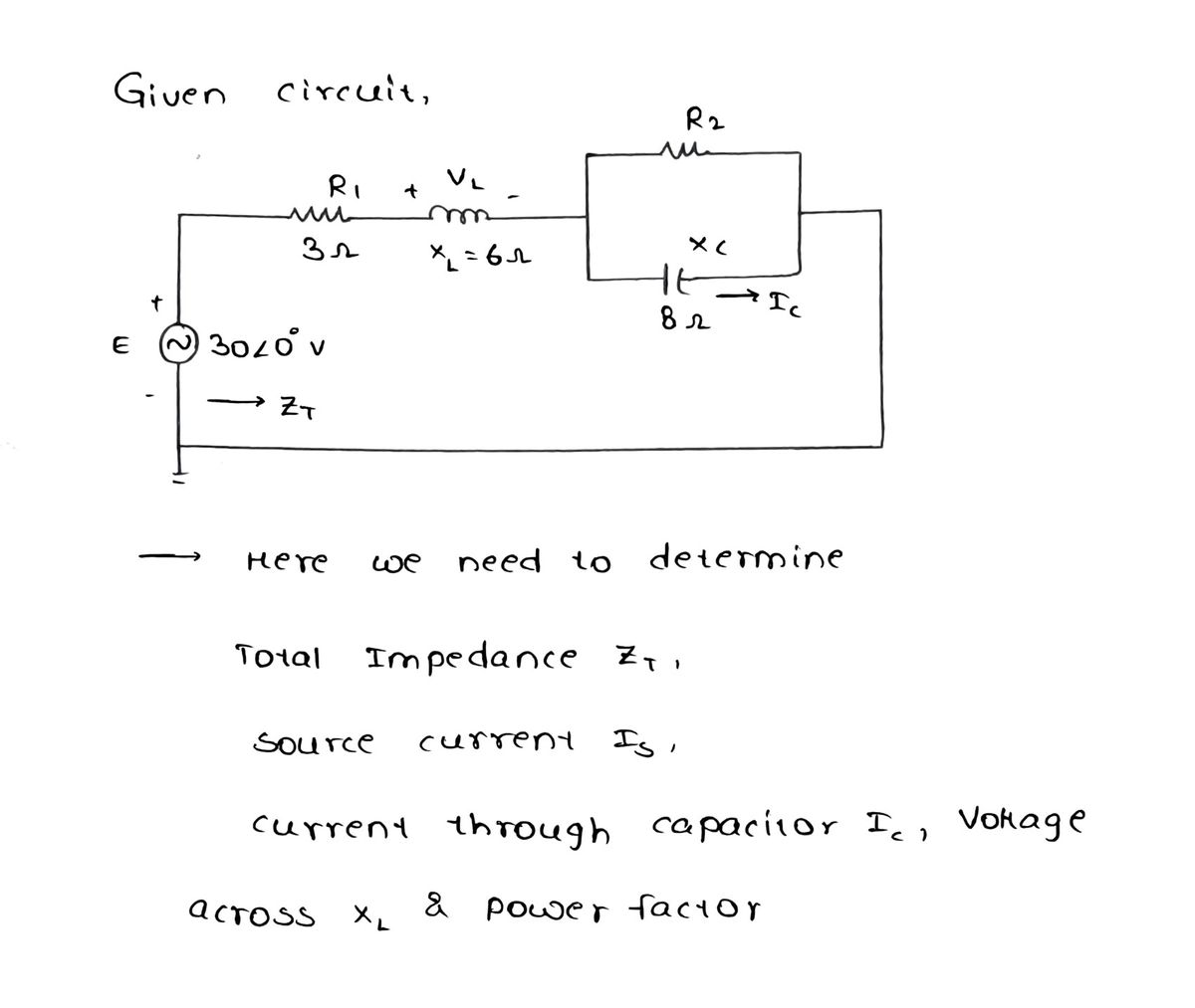
calcuate the following. Express your answer in polar notation

Transcribed Image Text:The image shows an AC circuit diagram with the following components and elements:
1. **Voltage Source \(E\):**
- \(E = 30V \angle 0^\circ\)
2. **Resistor \(R_1\):**
- Value: 3Ω
3. **Inductor \(X_L\):**
- Inductive reactance: 6Ω
- Tagged with voltage \(V_L\).
4. **Parallel Network:**
- Consisting of:
- **Resistor \(R_2\):** 2Ω
- **Capacitor \(X_C\):** Capacitive reactance of 8Ω, with current \(I_C\) flowing through it.
5. **Current and Impedance:**
- \(I_s\): Current across the circuit
- \(Z_T\): Total impedance of the circuit
6. **Blanks for Calculation Results:**
- \(Z_T = \_\_\_\_ \angle \_\_\_\_° \text{ units}\)
- \(I_s = \_\_\_\_ \angle \_\_\_\_° \text{ units}\)
- \(I_C = \_\_\_\_ \angle \_\_\_\_° \text{ units}\)
- \(V_L = \_\_\_\_ \angle \_\_\_\_° \text{ units}\)
- \( \text{pf} = \_\_\_\_ \text{lagging or leading}\)
This diagram is used to analyze AC circuits, focusing on the impedance, phase angles, and phasor quantities, which are important for understanding the behavior of AC power systems. The calculations involve determining the total impedance, the current flowing through different parts of the circuit, the voltage across the inductor, and the power factor which indicates the phase difference between the voltage and current.
Expert Solution
Step 1: Determine total impedance, Is, Ic, voltage across inductor, pf:

Step by step
Solved in 6 steps with 6 images

Knowledge Booster


Learn more about
Need a deep-dive on the concept behind this application? Look no further. Learn more about this topic, electrical-engineering and related others by exploring similar questions and additional content below.Recommended textbooks for you
Introductory Circuit Analysis (13th Edition)
Electrical Engineering
ISBN:
9780133923605
Author:
Robert L. Boylestad
Publisher:
PEARSON

Delmar's Standard Textbook Of Electricity
Electrical Engineering
ISBN:
9781337900348
Author:
Stephen L. Herman
Publisher:
Cengage Learning

Programmable Logic Controllers
Electrical Engineering
ISBN:
9780073373843
Author:
Frank D. Petruzella
Publisher:
McGraw-Hill Education
Introductory Circuit Analysis (13th Edition)
Electrical Engineering
ISBN:
9780133923605
Author:
Robert L. Boylestad
Publisher:
PEARSON
Delmar's Standard Textbook Of Electricity
Electrical Engineering
ISBN:
9781337900348
Author:
Stephen L. Herman
Publisher:
Cengage Learning
Programmable Logic Controllers
Electrical Engineering
ISBN:
9780073373843
Author:
Frank D. Petruzella
Publisher:
McGraw-Hill Education

Fundamentals of Electric Circuits
Electrical Engineering
ISBN:
9780078028229
Author:
Charles K Alexander, Matthew Sadiku
Publisher:
McGraw-Hill Education

Electric Circuits. (11th Edition)
Electrical Engineering
ISBN:
9780134746968
Author:
James W. Nilsson, Susan Riedel
Publisher:
PEARSON

Engineering Electromagnetics
Electrical Engineering
ISBN:
9780078028151
Author:
Hayt, William H. (william Hart), Jr, BUCK, John A.
Publisher:
Mcgraw-hill Education,