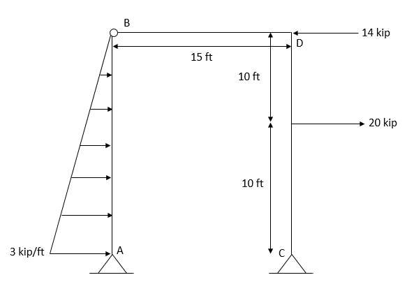
Draw the shear and moment diagrams of the frame and the deflected shape
Chapter2: Loads On Structures
Section: Chapter Questions
Problem 1P
Related questions
Question
Draw the shear and moment diagrams of the frame and the deflected shape

Transcribed Image Text:The image illustrates a structural frame with specific dimensions and applied forces. This diagram consists of a right-angle frame standing vertically and is labeled with three key points: A, B, and C.
### Key Features:
1. **Frame Dimensions**:
- The horizontal segment at the top of the frame measures 15 feet in length.
- Both vertical segments are 10 feet each in height.
2. **Force Indicators**:
- A 3 kips (3 k) force is applied horizontally at the base from point A toward the left.
- A horizontal force of 14 kips (14 k) is applied at the end of the top horizontal segment near point C, pointing to the right.
- At the midpoint of the right vertical segment from B to C (10 feet in height), a 20 kips (20 k) horizontal force acts to the right.
3. **Additional Features**:
- The left vertical segment is connected to the ground with a hinge at point B, which allows rotation or movement.
- Point B is located at the junction of the horizontal and left vertical segments, where the hinge is shown.
- A series of arrows depict the distributed force along the vertical segment from A to B.
This diagram can be used in engineering contexts to analyze the structural stability and force distribution within the frame.
Expert Solution
Step 1
Given:-

To find:-
Shear and moment diagram and the deflected shape
Trending now
This is a popular solution!
Step by step
Solved in 4 steps with 6 images

Recommended textbooks for you


Structural Analysis (10th Edition)
Civil Engineering
ISBN:
9780134610672
Author:
Russell C. Hibbeler
Publisher:
PEARSON

Principles of Foundation Engineering (MindTap Cou…
Civil Engineering
ISBN:
9781337705028
Author:
Braja M. Das, Nagaratnam Sivakugan
Publisher:
Cengage Learning


Structural Analysis (10th Edition)
Civil Engineering
ISBN:
9780134610672
Author:
Russell C. Hibbeler
Publisher:
PEARSON

Principles of Foundation Engineering (MindTap Cou…
Civil Engineering
ISBN:
9781337705028
Author:
Braja M. Das, Nagaratnam Sivakugan
Publisher:
Cengage Learning

Fundamentals of Structural Analysis
Civil Engineering
ISBN:
9780073398006
Author:
Kenneth M. Leet Emeritus, Chia-Ming Uang, Joel Lanning
Publisher:
McGraw-Hill Education


Traffic and Highway Engineering
Civil Engineering
ISBN:
9781305156241
Author:
Garber, Nicholas J.
Publisher:
Cengage Learning