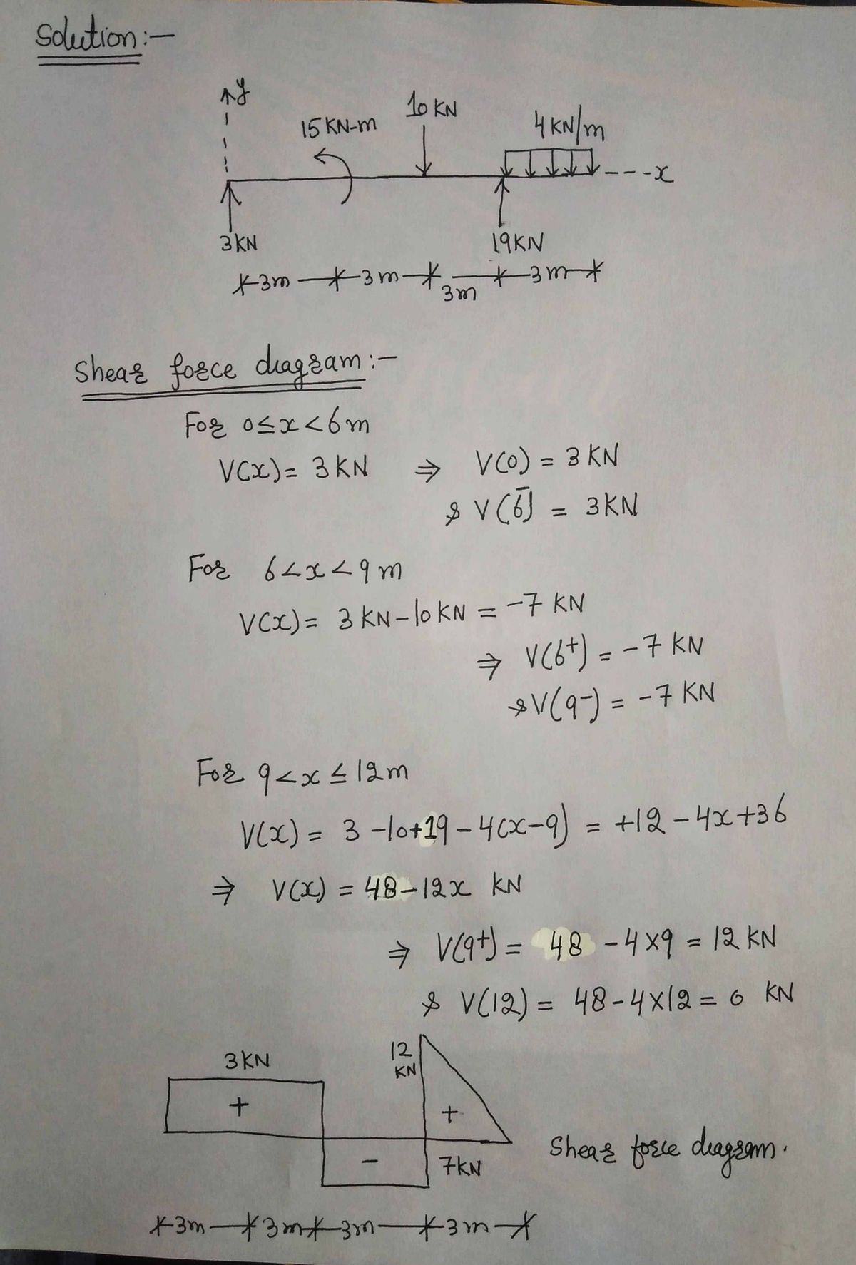
Draw the shear and moment diagram (show all work).
Chapter2: Loads On Structures
Section: Chapter Questions
Problem 1P
Related questions
Question
Draw the shear and moment diagram (show all work).
![### Structural Analysis of a Beam
This diagram represents a horizontal beam subjected to various forces and a moment. It is a typical problem used in mechanical or civil engineering to illustrate concepts related to static equilibrium and structural analysis.
#### Beam Description
The beam is laid out horizontally, aligned along the x-axis, with supports and loads as detailed below:
1. **Support at Point A (left side):**
- A pin support is shown providing a vertical reaction force of 3 kN upwards.
2. **Moment at Point A:**
- A 15 kN-m counterclockwise moment is applied at the point of support.
3. **Point Load at Mid-section:**
- There is a downward point load of 10 kN applied at a distance of 3 meters from the left support (point A).
4. **Distributed Load:**
- A uniformly distributed load of 4 kN/m spans across the right section of the beam, covering a length of 3 meters.
5. **Support at Point B (right side):**
- A roller support is shown with an upward reaction force of 19 kN.
#### Dimensions
- The beam is divided into equal segments of 3 meters each.
- The total length of the beam is 9 meters.
#### Explanation
The diagram illustrates the need to calculate reactions at the supports due to the external loads and moments. Analyzing the beam involves applying equilibrium equations to ensure that the sum of vertical forces and moments equals zero:
1. **Summation of Vertical Forces:**
\[
R_A + R_B = 3 \, \text{kN} + 19 \, \text{kN} = 22 \, \text{kN}
\]
Balanced by the downward point load and the distributed load.
2. **Moment Equilibrium:**
Taking moments about one of the supports (commonly done about point A to simplify calculations due to the moment present).
This visual representation aids in understanding how different loads affect structural elements, helping to ensure they are designed to remain safely within stress limits.](/v2/_next/image?url=https%3A%2F%2Fcontent.bartleby.com%2Fqna-images%2Fquestion%2Fcede8746-e52f-4eaf-bfc2-0cf286297e7e%2F2e28f1a4-4f55-4c60-b8cf-aa01363fe1e1%2Fa5x1qd5_processed.png&w=3840&q=75)
Transcribed Image Text:### Structural Analysis of a Beam
This diagram represents a horizontal beam subjected to various forces and a moment. It is a typical problem used in mechanical or civil engineering to illustrate concepts related to static equilibrium and structural analysis.
#### Beam Description
The beam is laid out horizontally, aligned along the x-axis, with supports and loads as detailed below:
1. **Support at Point A (left side):**
- A pin support is shown providing a vertical reaction force of 3 kN upwards.
2. **Moment at Point A:**
- A 15 kN-m counterclockwise moment is applied at the point of support.
3. **Point Load at Mid-section:**
- There is a downward point load of 10 kN applied at a distance of 3 meters from the left support (point A).
4. **Distributed Load:**
- A uniformly distributed load of 4 kN/m spans across the right section of the beam, covering a length of 3 meters.
5. **Support at Point B (right side):**
- A roller support is shown with an upward reaction force of 19 kN.
#### Dimensions
- The beam is divided into equal segments of 3 meters each.
- The total length of the beam is 9 meters.
#### Explanation
The diagram illustrates the need to calculate reactions at the supports due to the external loads and moments. Analyzing the beam involves applying equilibrium equations to ensure that the sum of vertical forces and moments equals zero:
1. **Summation of Vertical Forces:**
\[
R_A + R_B = 3 \, \text{kN} + 19 \, \text{kN} = 22 \, \text{kN}
\]
Balanced by the downward point load and the distributed load.
2. **Moment Equilibrium:**
Taking moments about one of the supports (commonly done about point A to simplify calculations due to the moment present).
This visual representation aids in understanding how different loads affect structural elements, helping to ensure they are designed to remain safely within stress limits.
Expert Solution
Step 1

Step by step
Solved in 2 steps with 2 images

Recommended textbooks for you


Structural Analysis (10th Edition)
Civil Engineering
ISBN:
9780134610672
Author:
Russell C. Hibbeler
Publisher:
PEARSON

Principles of Foundation Engineering (MindTap Cou…
Civil Engineering
ISBN:
9781337705028
Author:
Braja M. Das, Nagaratnam Sivakugan
Publisher:
Cengage Learning


Structural Analysis (10th Edition)
Civil Engineering
ISBN:
9780134610672
Author:
Russell C. Hibbeler
Publisher:
PEARSON

Principles of Foundation Engineering (MindTap Cou…
Civil Engineering
ISBN:
9781337705028
Author:
Braja M. Das, Nagaratnam Sivakugan
Publisher:
Cengage Learning

Fundamentals of Structural Analysis
Civil Engineering
ISBN:
9780073398006
Author:
Kenneth M. Leet Emeritus, Chia-Ming Uang, Joel Lanning
Publisher:
McGraw-Hill Education


Traffic and Highway Engineering
Civil Engineering
ISBN:
9781305156241
Author:
Garber, Nicholas J.
Publisher:
Cengage Learning