Determine the value of the support reactions at A and G. Use method of joint to find forces in member GA and GF. State if these members are in tension or compression.
Determine the value of the support reactions at A and G. Use method of joint to find forces in member GA and GF. State if these members are in tension or compression.

Elements Of Electromagnetics
7th Edition
ISBN:9780190698614
Author:Sadiku, Matthew N. O.
Publisher:Sadiku, Matthew N. O.
ChapterMA: Math Assessment
Section: Chapter Questions
Problem 1.1MA

Related questions
Question
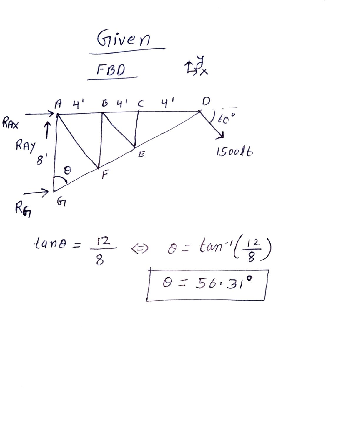
The truss system shown below is supported by a pin at A and a roller at G.
- Determine the value of the support reactions at A and G.
- Use method of joint to find forces in member GA and GF. State if these members are in tension or compression.

Transcribed Image Text:The diagram illustrates a truss system with several joints and members. The truss is anchored to a wall at points A and G.
- Horizontal Members: AB, BC, CD
- Vertical Members: AG
- Diagonal Members: AF, BE, CE, ED, FG
Dimensions:
- Each horizontal section (AB, BC, CD) measures 4 feet.
- The vertical height from point G to point A is 8 feet.
Forces:
- There is a 1500 lb external load applied at point D at a 60° angle downward to the right.
Triangle and Support:
- Point G and A are supported by fixed pin connections suggesting these are reaction points that prevent movement.
This is a typical structural analysis scenario used to teach students about forces in a truss system and how they are distributed across different members.
Expert Solution
Step 1: Given data

Step by step
Solved in 4 steps with 3 images

Knowledge Booster


Learn more about
Need a deep-dive on the concept behind this application? Look no further. Learn more about this topic, mechanical-engineering and related others by exploring similar questions and additional content below.Recommended textbooks for you
Elements Of Electromagnetics
Mechanical Engineering
ISBN:
9780190698614
Author:
Sadiku, Matthew N. O.
Publisher:
Oxford University Press

Mechanics of Materials (10th Edition)
Mechanical Engineering
ISBN:
9780134319650
Author:
Russell C. Hibbeler
Publisher:
PEARSON

Thermodynamics: An Engineering Approach
Mechanical Engineering
ISBN:
9781259822674
Author:
Yunus A. Cengel Dr., Michael A. Boles
Publisher:
McGraw-Hill Education
Elements Of Electromagnetics
Mechanical Engineering
ISBN:
9780190698614
Author:
Sadiku, Matthew N. O.
Publisher:
Oxford University Press
Mechanics of Materials (10th Edition)
Mechanical Engineering
ISBN:
9780134319650
Author:
Russell C. Hibbeler
Publisher:
PEARSON
Thermodynamics: An Engineering Approach
Mechanical Engineering
ISBN:
9781259822674
Author:
Yunus A. Cengel Dr., Michael A. Boles
Publisher:
McGraw-Hill Education

Control Systems Engineering
Mechanical Engineering
ISBN:
9781118170519
Author:
Norman S. Nise
Publisher:
WILEY

Mechanics of Materials (MindTap Course List)
Mechanical Engineering
ISBN:
9781337093347
Author:
Barry J. Goodno, James M. Gere
Publisher:
Cengage Learning

Engineering Mechanics: Statics
Mechanical Engineering
ISBN:
9781118807330
Author:
James L. Meriam, L. G. Kraige, J. N. Bolton
Publisher:
WILEY