Determine the force in menmbers CH and CF. -2 m -2 m 2 m -2 m E |A B 2 m (F 24 kN
Determine the force in menmbers CH and CF. -2 m -2 m 2 m -2 m E |A B 2 m (F 24 kN

Elements Of Electromagnetics
7th Edition
ISBN:9780190698614
Author:Sadiku, Matthew N. O.
Publisher:Sadiku, Matthew N. O.
ChapterMA: Math Assessment
Section: Chapter Questions
Problem 1.1MA

Related questions

Question
100%
Please help with the following problem

Transcribed Image Text:**Title: Truss Analysis: Determining Forces in Members CH and CF**
**Objective:**
To determine the forces in members CH and CF of the truss structure shown, using static equilibrium equations.
**Diagram Explanation:**
- The diagram illustrates a truss structure with joints labeled A, B, C, D, E, F, G, H, and I.
- The horizontal distances between each joint (A-B, B-C, C-D, D-E) are each 2 meters, making the total length 8 meters.
- The vertical distance from joint A to the support I is 2 meters.
- External forces of 24 kN are applied vertically downward at joints E, F, and G.
- The structure is supported at A and I, with I indicating a pin support, which allows rotation but not translation.
- Members of interest: CH and CF.
**Approach:**
1. **Static Equilibrium Equations**:
- Ensure the sum of all forces in the horizontal and vertical directions is zero.
- Ensure the sum of moments about any point is zero.
2. **Joint Method**:
- Analyze each joint starting from a joint with known forces or supports.
- Use equations of equilibrium to solve for unknown forces in each member.
3. **Member Forces**:
- Identify forces in members based on equilibrium conditions from adjacent joints.
- Determine whether the force is tensile or compressive.
This setup is a practical example for students learning structural analysis, emphasizing methodical problem-solving in engineering statics.
Expert Solution
Step 1
Pass the section directly through member CD, CF, and FG and analyze the portion of the truss to the right, because there are no supports or unknown reaction forces on the right section.
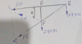
Assume all members are in tension.
Step 2
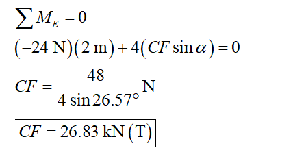
Determine the moment about point E and equate it to zero.

Step by step
Solved in 4 steps with 6 images

Knowledge Booster


Learn more about
Need a deep-dive on the concept behind this application? Look no further. Learn more about this topic, mechanical-engineering and related others by exploring similar questions and additional content below.Recommended textbooks for you
Elements Of Electromagnetics
Mechanical Engineering
ISBN:
9780190698614
Author:
Sadiku, Matthew N. O.
Publisher:
Oxford University Press

Mechanics of Materials (10th Edition)
Mechanical Engineering
ISBN:
9780134319650
Author:
Russell C. Hibbeler
Publisher:
PEARSON

Thermodynamics: An Engineering Approach
Mechanical Engineering
ISBN:
9781259822674
Author:
Yunus A. Cengel Dr., Michael A. Boles
Publisher:
McGraw-Hill Education
Elements Of Electromagnetics
Mechanical Engineering
ISBN:
9780190698614
Author:
Sadiku, Matthew N. O.
Publisher:
Oxford University Press
Mechanics of Materials (10th Edition)
Mechanical Engineering
ISBN:
9780134319650
Author:
Russell C. Hibbeler
Publisher:
PEARSON
Thermodynamics: An Engineering Approach
Mechanical Engineering
ISBN:
9781259822674
Author:
Yunus A. Cengel Dr., Michael A. Boles
Publisher:
McGraw-Hill Education

Control Systems Engineering
Mechanical Engineering
ISBN:
9781118170519
Author:
Norman S. Nise
Publisher:
WILEY

Mechanics of Materials (MindTap Course List)
Mechanical Engineering
ISBN:
9781337093347
Author:
Barry J. Goodno, James M. Gere
Publisher:
Cengage Learning

Engineering Mechanics: Statics
Mechanical Engineering
ISBN:
9781118807330
Author:
James L. Meriam, L. G. Kraige, J. N. Bolton
Publisher:
WILEY