Determine the force in member GF and state if the member is in tension or compression. Express your answer to three significant figures and include the appropriate units. Enter negative value in the case of compression and positive value in the case of tension. FGF= -15.0 kN Submit ✓ Correct Part B Previous Answers FCD= Determine the force in member CD and state if the member is in tension or compression. Express your answer to three significant figures and include the appropriate units. Enter negative value in the case of compression and positive value in the case of tension. μA Value Units Submit Previous Answers Request Answer P Pearson ? X Incorrect; Try Again; 13 attempts remaining Revie 2
Determine the force in member GF and state if the member is in tension or compression. Express your answer to three significant figures and include the appropriate units. Enter negative value in the case of compression and positive value in the case of tension. FGF= -15.0 kN Submit ✓ Correct Part B Previous Answers FCD= Determine the force in member CD and state if the member is in tension or compression. Express your answer to three significant figures and include the appropriate units. Enter negative value in the case of compression and positive value in the case of tension. μA Value Units Submit Previous Answers Request Answer P Pearson ? X Incorrect; Try Again; 13 attempts remaining Revie 2

Chapter2: Loads On Structures
Section: Chapter Questions
Problem 1P

Related questions

Question
![**Educational Content: Analyzing Member Forces in Structures**
**Task:**
Determine the force in member \( GF \) and state if the member is in tension or compression.
**Instructions:**
- Express your answer to three significant figures and include the appropriate units.
- Enter a negative value in the case of compression and a positive value in the case of tension.
**Response:**
\[ F_{GF} = -15.0 \, \text{kN} \]
*(✓ Correct)*
---
**Part B:**
**Task:**
Determine the force in member \( CD \) and state if the member is in tension or compression.
**Instructions:**
- Express your answer to three significant figures and include the appropriate units.
- Enter a negative value in the case of compression and a positive value in the case of tension.
**Response:**
\[ F_{CD} = \text{Value} \, \text{Units} \]
**Additional Features of the Interface:**
- Submission fields are provided for direct input of your answer.
- Feedback indicates if the response is correct or needs revision.
- A message displays the number of attempts remaining (13 attempts noted here).
**Provider Information:**
Content provided by Pearson. All rights reserved. Terms of Use and Privacy Policy are available for reference.](/v2/_next/image?url=https%3A%2F%2Fcontent.bartleby.com%2Fqna-images%2Fquestion%2Ff5fc9088-6d0a-4312-bffe-77961b56b51f%2Fa602e4d3-f8c0-4ff4-ab99-d6775596d89c%2Fzechc6b_processed.jpeg&w=3840&q=75)
Transcribed Image Text:**Educational Content: Analyzing Member Forces in Structures**
**Task:**
Determine the force in member \( GF \) and state if the member is in tension or compression.
**Instructions:**
- Express your answer to three significant figures and include the appropriate units.
- Enter a negative value in the case of compression and a positive value in the case of tension.
**Response:**
\[ F_{GF} = -15.0 \, \text{kN} \]
*(✓ Correct)*
---
**Part B:**
**Task:**
Determine the force in member \( CD \) and state if the member is in tension or compression.
**Instructions:**
- Express your answer to three significant figures and include the appropriate units.
- Enter a negative value in the case of compression and a positive value in the case of tension.
**Response:**
\[ F_{CD} = \text{Value} \, \text{Units} \]
**Additional Features of the Interface:**
- Submission fields are provided for direct input of your answer.
- Feedback indicates if the response is correct or needs revision.
- A message displays the number of attempts remaining (13 attempts noted here).
**Provider Information:**
Content provided by Pearson. All rights reserved. Terms of Use and Privacy Policy are available for reference.

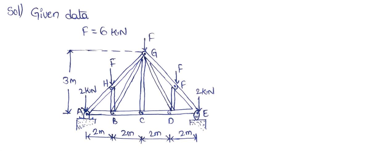
Transcribed Image Text:**Howe Truss Analysis**
The Howe truss is subjected to the loading shown in Figure 1. Suppose that \( F = 6 \, \text{kN} \).
**Figure Explanation**
This figure illustrates a Howe truss structure comprised of a series of interconnected beams, forming a triangular framework. The truss spans horizontally with supports at points \( A \) and \( E \). Distances between the vertical points B, C, and D are each 2 meters, and the overall truss height is 3 meters at the peak.
**Load Distribution:**
- At \( G \), a load \( F = 6 \, \text{kN} \) is applied vertically downward.
- Additional 6 kN loads are also applied vertically downward at points \( C \) and \( I \).
- Vertical reactions of 2 kN are present at support points \( A \) and \( E \).
The diagram is useful for illustrating load distribution and force analysis, relevant in structural engineering to understand the forces each member of the truss experiences.
Expert Solution
Step 1

Step by step
Solved in 3 steps with 3 images

Knowledge Booster


Learn more about
Need a deep-dive on the concept behind this application? Look no further. Learn more about this topic, civil-engineering and related others by exploring similar questions and additional content below.Recommended textbooks for you

Structural Analysis (10th Edition)
Civil Engineering
ISBN:
9780134610672
Author:
Russell C. Hibbeler
Publisher:
PEARSON

Principles of Foundation Engineering (MindTap Cou…
Civil Engineering
ISBN:
9781337705028
Author:
Braja M. Das, Nagaratnam Sivakugan
Publisher:
Cengage Learning
Structural Analysis (10th Edition)
Civil Engineering
ISBN:
9780134610672
Author:
Russell C. Hibbeler
Publisher:
PEARSON
Principles of Foundation Engineering (MindTap Cou…
Civil Engineering
ISBN:
9781337705028
Author:
Braja M. Das, Nagaratnam Sivakugan
Publisher:
Cengage Learning

Fundamentals of Structural Analysis
Civil Engineering
ISBN:
9780073398006
Author:
Kenneth M. Leet Emeritus, Chia-Ming Uang, Joel Lanning
Publisher:
McGraw-Hill Education


Traffic and Highway Engineering
Civil Engineering
ISBN:
9781305156241
Author:
Garber, Nicholas J.
Publisher:
Cengage Learning