Determine the base-bias voltage (Vbias) required to sink 1.5 mA for the circuit shown in Figure 5-56 (p. 250). IS =1.3 x 10⁻¹³ A and the temperature is 27°C.
Determine the base-bias voltage (Vbias) required to sink 1.5 mA for the circuit shown in Figure 5-56 (p. 250). IS =1.3 x 10⁻¹³ A and the temperature is 27°C.

Introductory Circuit Analysis (13th Edition)
13th Edition
ISBN:9780133923605
Author:Robert L. Boylestad
Publisher:Robert L. Boylestad
Chapter1: Introduction
Section: Chapter Questions
Problem 1P: Visit your local library (at school or home) and describe the extent to which it provides literature...

Related questions

Question
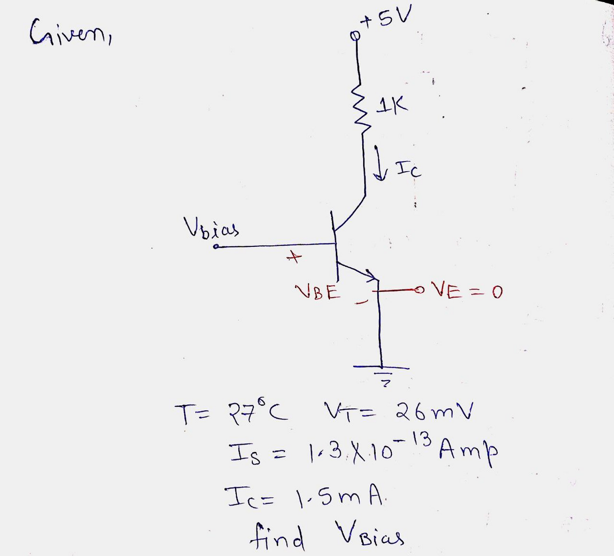
Determine the base-bias voltage (Vbias) required to sink 1.5 mA for the circuit shown in Figure 5-56 (p. 250). IS =1.3 x 10⁻¹³ A and the temperature is 27°C.

Transcribed Image Text:**Transcription and Explanation for Educational Use:**
The diagram in Figure 5-56 illustrates a simple transistor circuit, which is related to Exercise 5-5.
**Components and Connections:**
- **Voltage Source (+5 V):** The circuit is connected to a +5 V power supply at the top.
- **Resistor (1 KΩ):** A 1 kilo-ohm resistor is connected in series with the power supply. This resistor limits the current flowing through the circuit.
- **Transistor:** The transistor is depicted with its three terminals labeled appropriately. The part of the transistor interacting with current flow is marked.
- **V_bias:** This is the input or base voltage applied to the transistor's base terminal.
- **Ground Connection:** The emitter terminal of the transistor is connected to the ground.
- **Current Notation (I_C):** The current flowing from the collector to the emitter of the transistor is labeled I_C.
**Function of the Circuit:**
This specific configuration demonstrates how a transistor can be used to control current flow. The base voltage (V_bias) influences the current (I_C) flowing through the collector-emitter path, regulated by the 1 KΩ resistor connected to the power supply. This setup might be used to understand transistor biasing and amplification principles in educational exercises.
Expert Solution
Step 1

Step by step
Solved in 2 steps with 2 images

Knowledge Booster


Learn more about
Need a deep-dive on the concept behind this application? Look no further. Learn more about this topic, electrical-engineering and related others by exploring similar questions and additional content below.Recommended textbooks for you
Introductory Circuit Analysis (13th Edition)
Electrical Engineering
ISBN:
9780133923605
Author:
Robert L. Boylestad
Publisher:
PEARSON

Delmar's Standard Textbook Of Electricity
Electrical Engineering
ISBN:
9781337900348
Author:
Stephen L. Herman
Publisher:
Cengage Learning

Programmable Logic Controllers
Electrical Engineering
ISBN:
9780073373843
Author:
Frank D. Petruzella
Publisher:
McGraw-Hill Education
Introductory Circuit Analysis (13th Edition)
Electrical Engineering
ISBN:
9780133923605
Author:
Robert L. Boylestad
Publisher:
PEARSON
Delmar's Standard Textbook Of Electricity
Electrical Engineering
ISBN:
9781337900348
Author:
Stephen L. Herman
Publisher:
Cengage Learning
Programmable Logic Controllers
Electrical Engineering
ISBN:
9780073373843
Author:
Frank D. Petruzella
Publisher:
McGraw-Hill Education

Fundamentals of Electric Circuits
Electrical Engineering
ISBN:
9780078028229
Author:
Charles K Alexander, Matthew Sadiku
Publisher:
McGraw-Hill Education

Electric Circuits. (11th Edition)
Electrical Engineering
ISBN:
9780134746968
Author:
James W. Nilsson, Susan Riedel
Publisher:
PEARSON

Engineering Electromagnetics
Electrical Engineering
ISBN:
9780078028151
Author:
Hayt, William H. (william Hart), Jr, BUCK, John A.
Publisher:
Mcgraw-hill Education,