Determine node voltages in the following circuit. 30 V 2Ω 2 2Ω 1 3 4Ω 15 A 8Ω
Determine node voltages in the following circuit. 30 V 2Ω 2 2Ω 1 3 4Ω 15 A 8Ω

Introductory Circuit Analysis (13th Edition)
13th Edition
ISBN:9780133923605
Author:Robert L. Boylestad
Publisher:Robert L. Boylestad
Chapter1: Introduction
Section: Chapter Questions
Problem 1P: Visit your local library (at school or home) and describe the extent to which it provides literature...

Related questions
Question
100%

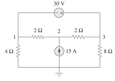
Transcribed Image Text:The problem poses the task: "Determine node voltages in the following circuit."
The circuit diagram includes the following components:
1. **Voltage Source**:
- A 30 V independent voltage source is at the top of the circuit, connected between node 1 and node 3.
2. **Resistors**:
- A 2Ω resistor is connected between nodes 1 and 2.
- Another 2Ω resistor is placed between nodes 2 and 3.
- A 4Ω resistor is connected between node 1 and the ground.
- An 8Ω resistor is connected between node 3 and the ground.
3. **Current Source**:
- A 15 A current source is directed downward at node 2, connected to the ground.
4. **Nodes**:
- Node 1 is at the junction of the 2Ω resistor (to the left) and the 4Ω resistor.
- Node 2 is at the junction of the two 2Ω resistors with a downward 15 A current source.
- Node 3 is at the junction of the 2Ω and 8Ω resistors.
These components form a simple electrical circuit. The task involves calculating the voltages at nodes 1, 2, and 3 with respect to the ground using node voltage analysis.
Expert Solution
Step 1
Given circuit,

Step by step
Solved in 2 steps with 2 images

Recommended textbooks for you
Introductory Circuit Analysis (13th Edition)
Electrical Engineering
ISBN:
9780133923605
Author:
Robert L. Boylestad
Publisher:
PEARSON

Delmar's Standard Textbook Of Electricity
Electrical Engineering
ISBN:
9781337900348
Author:
Stephen L. Herman
Publisher:
Cengage Learning

Programmable Logic Controllers
Electrical Engineering
ISBN:
9780073373843
Author:
Frank D. Petruzella
Publisher:
McGraw-Hill Education
Introductory Circuit Analysis (13th Edition)
Electrical Engineering
ISBN:
9780133923605
Author:
Robert L. Boylestad
Publisher:
PEARSON
Delmar's Standard Textbook Of Electricity
Electrical Engineering
ISBN:
9781337900348
Author:
Stephen L. Herman
Publisher:
Cengage Learning
Programmable Logic Controllers
Electrical Engineering
ISBN:
9780073373843
Author:
Frank D. Petruzella
Publisher:
McGraw-Hill Education

Fundamentals of Electric Circuits
Electrical Engineering
ISBN:
9780078028229
Author:
Charles K Alexander, Matthew Sadiku
Publisher:
McGraw-Hill Education

Electric Circuits. (11th Edition)
Electrical Engineering
ISBN:
9780134746968
Author:
James W. Nilsson, Susan Riedel
Publisher:
PEARSON

Engineering Electromagnetics
Electrical Engineering
ISBN:
9780078028151
Author:
Hayt, William H. (william Hart), Jr, BUCK, John A.
Publisher:
Mcgraw-hill Education,