(Create truth table before multiplexer), list the inputs for the following configuration. Final Circuit BC IO DIU U IAIA A A
(Create truth table before multiplexer), list the inputs for the following configuration. Final Circuit BC IO DIU U IAIA A A

Introductory Circuit Analysis (13th Edition)
13th Edition
ISBN:9780133923605
Author:Robert L. Boylestad
Publisher:Robert L. Boylestad
Chapter1: Introduction
Section: Chapter Questions
Problem 1P: Visit your local library (at school or home) and describe the extent to which it provides literature...

Related questions
Question
![### Implementing a Function Via Multiplexer (Using B & C as Switches)
#### Function Specification
- **Function to Implement:**
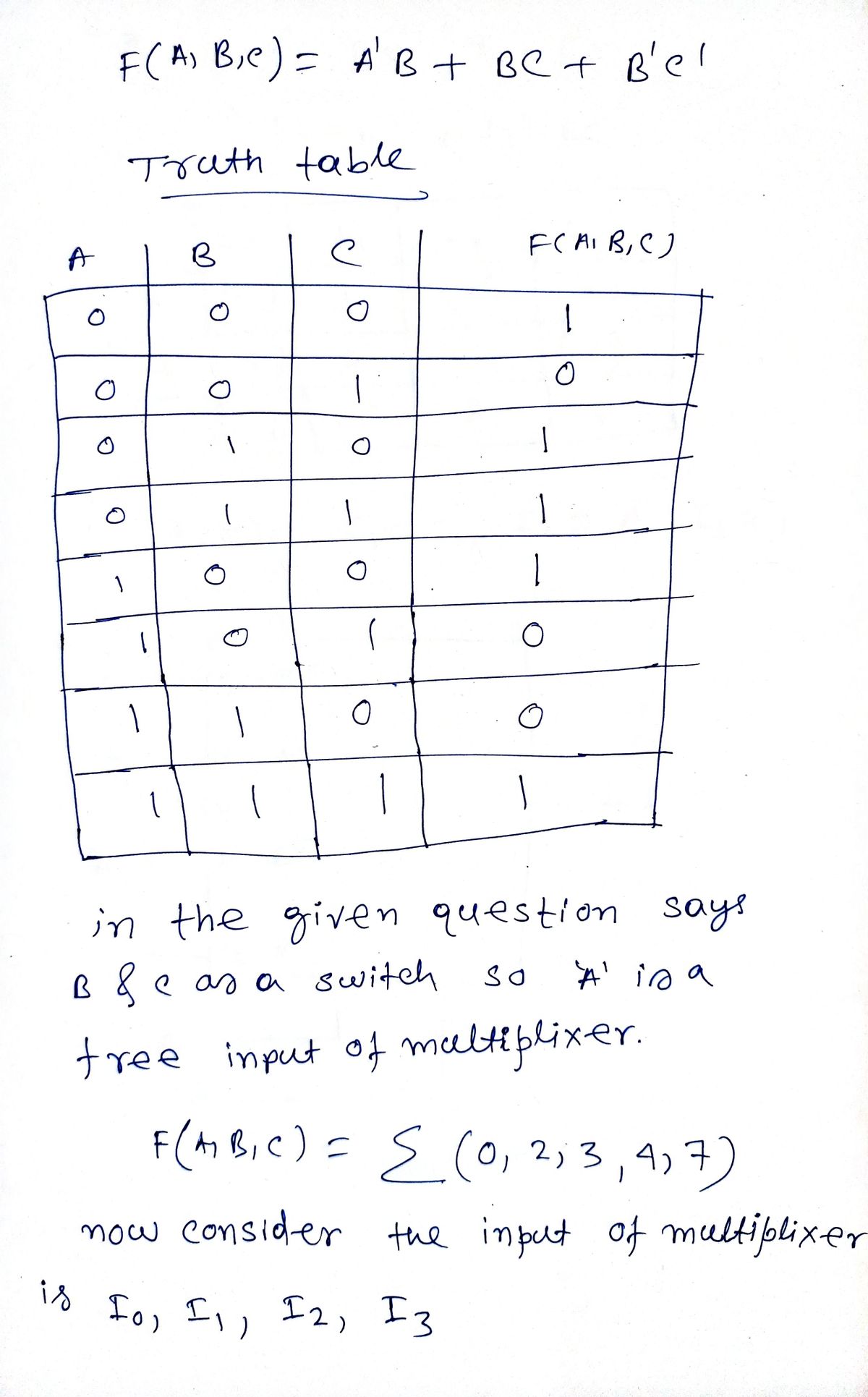
\[ F(A, B, C) = A'B + BC + B'C' \]
#### Instructions
- **Objective:** Implement the specified function using a multiplexer with B and C as control switches.
- **Required:** Create a truth table before connecting the multiplexer and list the inputs for the given configuration.
#### Diagram Explanation
- **Diagram Title:** Final Circuit
- **Components:**
- A multiplexer with four data inputs. Each input corresponds to a combination of control signals \( B \) and \( C \):
- Input for \( \overline{B}\overline{C} \)
- Input for \( \overline{B}C \)
- Input for \( B\overline{C} \)
- Input for \( BC \)
- Two control lines are labeled as \( B \) and \( C \), which determine the input that is passed to the output \( f \).
#### Implementation Steps
1. **Truth Table Creation:**
- Construct a truth table for \( F(A, B, C) \) showing all possible combinations of inputs (A, B, C) and the resultant output F.
2. **Input Listing:**
- Determine the appropriate inputs that need to be connected to each line of the multiplexer for it to accurately represent the given function.
3. **Multiplexer Configuration:**
- Connect the outputs from the truth table to the respective inputs on the multiplexer as determined by the expressions for \( \overline{B}\overline{C} \), \( \overline{B}C \), \( B\overline{C} \), and \( BC \).
By following these guidelines, the logical function \( F(A, B, C) \) can be implemented effectively using a multiplexer.](/v2/_next/image?url=https%3A%2F%2Fcontent.bartleby.com%2Fqna-images%2Fquestion%2F28d87aad-9c30-4a0c-a50c-2652b053b249%2F1bc55f40-1339-4c83-9f83-ed97a2bfc9c0%2Fgr0yfsu_processed.png&w=3840&q=75)
Transcribed Image Text:### Implementing a Function Via Multiplexer (Using B & C as Switches)
#### Function Specification
- **Function to Implement:**
\[ F(A, B, C) = A'B + BC + B'C' \]
#### Instructions
- **Objective:** Implement the specified function using a multiplexer with B and C as control switches.
- **Required:** Create a truth table before connecting the multiplexer and list the inputs for the given configuration.
#### Diagram Explanation
- **Diagram Title:** Final Circuit
- **Components:**
- A multiplexer with four data inputs. Each input corresponds to a combination of control signals \( B \) and \( C \):
- Input for \( \overline{B}\overline{C} \)
- Input for \( \overline{B}C \)
- Input for \( B\overline{C} \)
- Input for \( BC \)
- Two control lines are labeled as \( B \) and \( C \), which determine the input that is passed to the output \( f \).
#### Implementation Steps
1. **Truth Table Creation:**
- Construct a truth table for \( F(A, B, C) \) showing all possible combinations of inputs (A, B, C) and the resultant output F.
2. **Input Listing:**
- Determine the appropriate inputs that need to be connected to each line of the multiplexer for it to accurately represent the given function.
3. **Multiplexer Configuration:**
- Connect the outputs from the truth table to the respective inputs on the multiplexer as determined by the expressions for \( \overline{B}\overline{C} \), \( \overline{B}C \), \( B\overline{C} \), and \( BC \).
By following these guidelines, the logical function \( F(A, B, C) \) can be implemented effectively using a multiplexer.
Expert Solution
Step 1

Step by step
Solved in 2 steps with 2 images

Recommended textbooks for you
Introductory Circuit Analysis (13th Edition)
Electrical Engineering
ISBN:
9780133923605
Author:
Robert L. Boylestad
Publisher:
PEARSON

Delmar's Standard Textbook Of Electricity
Electrical Engineering
ISBN:
9781337900348
Author:
Stephen L. Herman
Publisher:
Cengage Learning

Programmable Logic Controllers
Electrical Engineering
ISBN:
9780073373843
Author:
Frank D. Petruzella
Publisher:
McGraw-Hill Education
Introductory Circuit Analysis (13th Edition)
Electrical Engineering
ISBN:
9780133923605
Author:
Robert L. Boylestad
Publisher:
PEARSON
Delmar's Standard Textbook Of Electricity
Electrical Engineering
ISBN:
9781337900348
Author:
Stephen L. Herman
Publisher:
Cengage Learning
Programmable Logic Controllers
Electrical Engineering
ISBN:
9780073373843
Author:
Frank D. Petruzella
Publisher:
McGraw-Hill Education

Fundamentals of Electric Circuits
Electrical Engineering
ISBN:
9780078028229
Author:
Charles K Alexander, Matthew Sadiku
Publisher:
McGraw-Hill Education

Electric Circuits. (11th Edition)
Electrical Engineering
ISBN:
9780134746968
Author:
James W. Nilsson, Susan Riedel
Publisher:
PEARSON

Engineering Electromagnetics
Electrical Engineering
ISBN:
9780078028151
Author:
Hayt, William H. (william Hart), Jr, BUCK, John A.
Publisher:
Mcgraw-hill Education,