Consider the Circuit shown 10mA How much To t=o energy 2kn 8.2 kn 2 kn + V₂ ell İL 10 mH 20 mH Find an expression for in and V₁ if the switch is closed at t = os. is stored in each inductor ? LINO 200
Consider the Circuit shown 10mA How much To t=o energy 2kn 8.2 kn 2 kn + V₂ ell İL 10 mH 20 mH Find an expression for in and V₁ if the switch is closed at t = os. is stored in each inductor ? LINO 200

Introductory Circuit Analysis (13th Edition)
13th Edition
ISBN:9780133923605
Author:Robert L. Boylestad
Publisher:Robert L. Boylestad
Chapter1: Introduction
Section: Chapter Questions
Problem 1P: Visit your local library (at school or home) and describe the extent to which it provides literature...

Related questions
Question
Can you please answers both wu
![**Problem Description:**
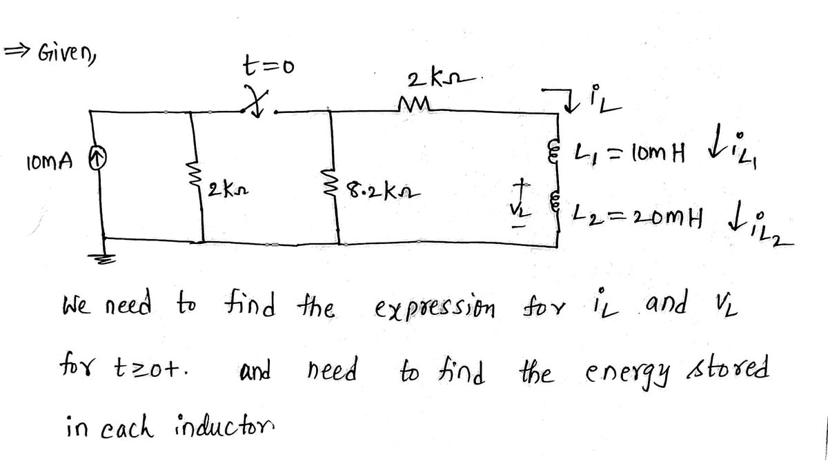
Consider the circuit shown in the diagram.
**Circuit Details:**
- A 10 mA current source is connected in series with a 2 kΩ resistor and a parallel combination of another 2 kΩ resistor and an 8.2 kΩ resistor.
- A switch is placed in the circuit at \( t = 0 \).
- After the switch, there is a series connection to a 2 kΩ resistor.
- This leads to two inductors, one is 10 mH and the other is 20 mH, connected in series with each other.
- The current through the inductors is labeled \( i_L \) and the voltage across them is labeled \( V_L \).
**Tasks:**
1. Find an expression for \( i_L \) and \( V_L \) if the switch is closed at \( t = 0 \).
2. Calculate how much energy is stored in each inductor.
**Solution Approach:**
To solve these questions, apply the following steps:
- Analyze the circuit initially for \( t < 0 \) and for \( t \geq 0 \) when the switch is closed.
- Use Kirchhoff's laws and the properties of inductors to form differential equations as needed.
- For energy stored in the inductors, use the formula:
\[ \text{Energy} = \frac{1}{2} L i^2 \]
where \( L \) is the inductance and \( i \) is the current through the inductor at the steady state.
This approach will help derive the expressions for \( i_L \) and \( V_L \), and calculate the energy for each inductor individually.](/v2/_next/image?url=https%3A%2F%2Fcontent.bartleby.com%2Fqna-images%2Fquestion%2F3a1a8c69-ac20-486b-9f67-8f66504c5494%2Fbc0d2022-9ea1-4bbd-a326-19688b7b5fc4%2Fljw90ja_processed.jpeg&w=3840&q=75)
Transcribed Image Text:**Problem Description:**
Consider the circuit shown in the diagram.
**Circuit Details:**
- A 10 mA current source is connected in series with a 2 kΩ resistor and a parallel combination of another 2 kΩ resistor and an 8.2 kΩ resistor.
- A switch is placed in the circuit at \( t = 0 \).
- After the switch, there is a series connection to a 2 kΩ resistor.
- This leads to two inductors, one is 10 mH and the other is 20 mH, connected in series with each other.
- The current through the inductors is labeled \( i_L \) and the voltage across them is labeled \( V_L \).
**Tasks:**
1. Find an expression for \( i_L \) and \( V_L \) if the switch is closed at \( t = 0 \).
2. Calculate how much energy is stored in each inductor.
**Solution Approach:**
To solve these questions, apply the following steps:
- Analyze the circuit initially for \( t < 0 \) and for \( t \geq 0 \) when the switch is closed.
- Use Kirchhoff's laws and the properties of inductors to form differential equations as needed.
- For energy stored in the inductors, use the formula:
\[ \text{Energy} = \frac{1}{2} L i^2 \]
where \( L \) is the inductance and \( i \) is the current through the inductor at the steady state.
This approach will help derive the expressions for \( i_L \) and \( V_L \), and calculate the energy for each inductor individually.
Expert Solution
Step 1: State the given data.

Step by step
Solved in 6 steps with 6 images

Knowledge Booster


Learn more about
Need a deep-dive on the concept behind this application? Look no further. Learn more about this topic, electrical-engineering and related others by exploring similar questions and additional content below.Recommended textbooks for you
Introductory Circuit Analysis (13th Edition)
Electrical Engineering
ISBN:
9780133923605
Author:
Robert L. Boylestad
Publisher:
PEARSON

Delmar's Standard Textbook Of Electricity
Electrical Engineering
ISBN:
9781337900348
Author:
Stephen L. Herman
Publisher:
Cengage Learning

Programmable Logic Controllers
Electrical Engineering
ISBN:
9780073373843
Author:
Frank D. Petruzella
Publisher:
McGraw-Hill Education
Introductory Circuit Analysis (13th Edition)
Electrical Engineering
ISBN:
9780133923605
Author:
Robert L. Boylestad
Publisher:
PEARSON
Delmar's Standard Textbook Of Electricity
Electrical Engineering
ISBN:
9781337900348
Author:
Stephen L. Herman
Publisher:
Cengage Learning
Programmable Logic Controllers
Electrical Engineering
ISBN:
9780073373843
Author:
Frank D. Petruzella
Publisher:
McGraw-Hill Education

Fundamentals of Electric Circuits
Electrical Engineering
ISBN:
9780078028229
Author:
Charles K Alexander, Matthew Sadiku
Publisher:
McGraw-Hill Education

Electric Circuits. (11th Edition)
Electrical Engineering
ISBN:
9780134746968
Author:
James W. Nilsson, Susan Riedel
Publisher:
PEARSON

Engineering Electromagnetics
Electrical Engineering
ISBN:
9780078028151
Author:
Hayt, William H. (william Hart), Jr, BUCK, John A.
Publisher:
Mcgraw-hill Education,