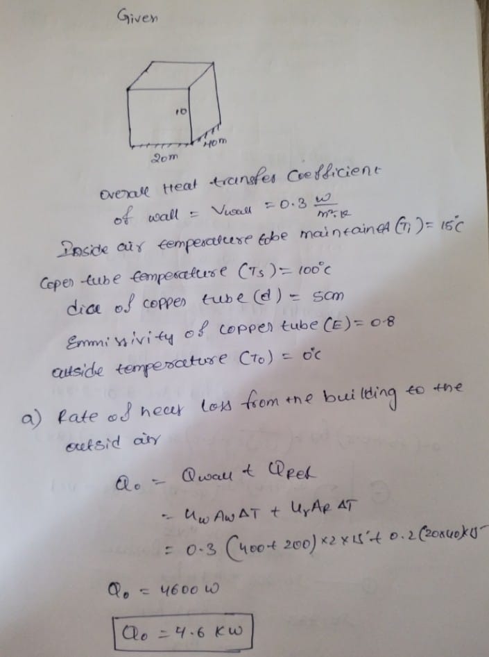
Consider a rectangular warehouse with the dimensions of 40m long x 20m widex10m height. The overall heat transfer coefficient for all sidewalls is Uwall=0.3 W/m2K (Approx. R=20 hr.ft2.oF/Btu) and for the flat roof, it is Uroof= 0.20W/m2K. The floor can be assumed to be insulated and we can ignore the heat transfer through the doors, etc. We want to maintain the inside air temperature at 15oC while the outside temperature is 0oC by using a thin-walled, 5.0cm diameter copper pipe that carries steam. Steam enters the pipe as saturated vapor at 100oC. So, as it starts losing heat to the inside air, it starts to condense. The thin-walled pipe is made of, a highly conductive material such that the outside temperature of the pipe is at 100oC steam temperature over its entire surface. The average emissivity of the pipe is 0.8 and the only radiative exchange is with the air inside of the building at 15oC. We want to determine the length of the pipe necessary to keep the inside temperature at the desired level. a) What is the rate of heat loss from the building to the outside air in Watts (or kW)? b) In determining the length of the pipe, we can allow steam to only condense to saturated liquid at 100oC with no further cooling. Therefore, the entire outside surface temperature of the pipe is at the saturation temperature of 100oC. If the heat of condensation for steam is 2,500 kJ/kg, what should be the rate of condensing steam flow necessary to meet the heat loss of the building kg/hr? c) Consider that the air inside the building is quiescent/calm and that the mode of heat transfer from the outside surface of the pipe to the room is by "Natural Convection" and Radiationonly. What is the rate of heat supply to the inside air per meter length of the pipe? d) What is the total length of the pipe needed to meet the heat loss in meters?
Consider a rectangular warehouse with the dimensions of 40m long x 20m widex10m height. The overall heat transfer coefficient for all sidewalls is Uwall=0.3 W/m2K (Approx. R=20 hr.ft2.oF/Btu) and for the flat roof, it is Uroof= 0.20W/m2K. The floor can be assumed to be insulated and we can ignore the heat transfer through the doors, etc. We want to maintain the inside air temperature at 15oC while the outside temperature is 0oC by using a thin-walled, 5.0cm diameter copper pipe that carries steam. Steam enters the pipe as saturated vapor at 100oC. So, as it starts losing heat to the inside air, it starts to condense. The thin-walled pipe is made of, a highly conductive material such that the outside temperature of the pipe is at 100oC steam temperature over its entire surface. The average emissivity of the pipe is 0.8 and the only radiative exchange is with the air inside of the building at 15oC. We want to determine the length of the pipe necessary to keep the inside temperature at the desired level.
a) What is the rate of heat loss from the building to the outside air in Watts (or kW)?
b) In determining the length of the pipe, we can allow steam to only condense to saturated liquid at 100oC with no further cooling. Therefore, the entire outside surface temperature of the pipe is at the saturation temperature of 100oC. If the heat of condensation for steam is 2,500 kJ/kg, what should be the rate of condensing steam flow necessary to meet the heat loss of the building kg/hr?
c) Consider that the air inside the building is quiescent/calm and that the mode of heat transfer from the outside surface of the pipe to the room is by "Natural Convection" and Radiationonly. What is the rate of heat supply to the inside air per meter length of the pipe?
d) What is the total length of the pipe needed to meet the heat loss in meters?
e) We now want to increase heat transfer by placing fans to provide forced convection to reduce the length of the pipe necessary (Note that the outside surface temperature of the pipe remains the same at 100oC). What is the rate of heat transfer from pipe to the air per meter length if the air speed over the pipe surface is 5m/s? What is the total length of the pipe necessary?
![The provided image contains two mathematical equations related to dimensionless numbers often used in fluid dynamics:
1. **Rayleigh Number (Ra\_D):**
\[
Ra_D = \frac{g \beta (T_s - T_\infty) D^3}{\alpha \nu}
\]
- **g**: Acceleration due to gravity
- **β**: Thermal expansion coefficient
- **T_s**: Surface temperature
- **T_∞**: Ambient temperature
- **D**: Characteristic length or diameter
- **α**: Thermal diffusivity
- **ν**: Kinematic viscosity
This formula is used to characterize the flow regime in natural convection. It considers buoyancy and thermal diffusion effects.
2. **Reynolds Number (Re\_D):**
\[
Re_D = \frac{Vel \times D}{\nu}
\]
- **Vel**: Velocity of the fluid
- **D**: Characteristic length or diameter
- **ν**: Kinematic viscosity
The Reynolds number helps to predict flow patterns in different fluid flow situations, indicating whether the flow will be laminar or turbulent.
There are no graphs or diagrams accompanying these equations in the image.](/v2/_next/image?url=https%3A%2F%2Fcontent.bartleby.com%2Fqna-images%2Fquestion%2F368d064c-ece9-4358-9be9-95ab5c57dddf%2F52292b5a-8d5a-4c25-9ffc-482942aa3b0c%2Fnymtcz_processed.png&w=3840&q=75)

As per BARTLEBY rules i answer only first three sub parts. so i hope you understand.

.jpg)
.jpg)
Step by step
Solved in 2 steps with 4 images


