Circuit Description: Assume you have a balanced 3-phase system. The sources have an abc sequence and are Y-connected. Von=120 20°VRMS. There is no internal source impedance or line impedance. The source feeds 2 Y-connected loads in parallel. The impedance of load 1 is 4+j32/4. The complex power for the a- phase of load 2 is 300 36 ° VA.
Circuit Description: Assume you have a balanced 3-phase system. The sources have an abc sequence and are Y-connected. Von=120 20°VRMS. There is no internal source impedance or line impedance. The source feeds 2 Y-connected loads in parallel. The impedance of load 1 is 4+j32/4. The complex power for the a- phase of load 2 is 300 36 ° VA.

Introductory Circuit Analysis (13th Edition)
13th Edition
ISBN:9780133923605
Author:Robert L. Boylestad
Publisher:Robert L. Boylestad
Chapter1: Introduction
Section: Chapter Questions
Problem 1P: Visit your local library (at school or home) and describe the extent to which it provides literature...

Related questions
Question
100%
Someone already did this problem but with the wrong values that weren't give? How can I get a question back when they were completely wrong? But need help.

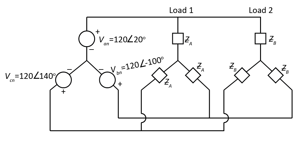
Transcribed Image Text:Draw the complete 3-phase circuit, in the phasor domain, noting the unknown load 2 as Zin each
phase. Redraw just the a-phase of the circuit and calculate impedance of load 2 based on the
ihformetion provided, the velitage aeross the loads (VAN) and the current through the a-phase. What is
the total complex power supplied by the source? If the source frequency is 60 Hz, what component
values should be used for the 2 loads?

Transcribed Image Text:Circuit Description:
Assume you have a balanced 3-phase system. The sources have an abc sequence and are Y-connected.
V an=120Z 20°VRMS. There is no internal source impedance or line impedance. The source feeds 2
Y-connected loads in parallel. The impedance of load 1 is 4+ j 3 2/4. The complex power for the a-
phase of load 2 is 300 36 °VA.
Expert Solution
Step 1
Given data,

Trending now
This is a popular solution!

Step by step
Solved in 4 steps with 1 images

Knowledge Booster


Learn more about
Need a deep-dive on the concept behind this application? Look no further. Learn more about this topic, electrical-engineering and related others by exploring similar questions and additional content below.Recommended textbooks for you
Introductory Circuit Analysis (13th Edition)
Electrical Engineering
ISBN:
9780133923605
Author:
Robert L. Boylestad
Publisher:
PEARSON

Delmar's Standard Textbook Of Electricity
Electrical Engineering
ISBN:
9781337900348
Author:
Stephen L. Herman
Publisher:
Cengage Learning

Programmable Logic Controllers
Electrical Engineering
ISBN:
9780073373843
Author:
Frank D. Petruzella
Publisher:
McGraw-Hill Education
Introductory Circuit Analysis (13th Edition)
Electrical Engineering
ISBN:
9780133923605
Author:
Robert L. Boylestad
Publisher:
PEARSON
Delmar's Standard Textbook Of Electricity
Electrical Engineering
ISBN:
9781337900348
Author:
Stephen L. Herman
Publisher:
Cengage Learning
Programmable Logic Controllers
Electrical Engineering
ISBN:
9780073373843
Author:
Frank D. Petruzella
Publisher:
McGraw-Hill Education

Fundamentals of Electric Circuits
Electrical Engineering
ISBN:
9780078028229
Author:
Charles K Alexander, Matthew Sadiku
Publisher:
McGraw-Hill Education

Electric Circuits. (11th Edition)
Electrical Engineering
ISBN:
9780134746968
Author:
James W. Nilsson, Susan Riedel
Publisher:
PEARSON

Engineering Electromagnetics
Electrical Engineering
ISBN:
9780078028151
Author:
Hayt, William H. (william Hart), Jr, BUCK, John A.
Publisher:
Mcgraw-hill Education,