Calculate the voltage current and power of each element.

Introductory Circuit Analysis (13th Edition)
13th Edition
ISBN:9780133923605
Author:Robert L. Boylestad
Publisher:Robert L. Boylestad
Chapter1: Introduction
Section: Chapter Questions
Problem 1P: Visit your local library (at school or home) and describe the extent to which it provides literature...

Related questions

Question
Calculate the voltage current and power of each element.

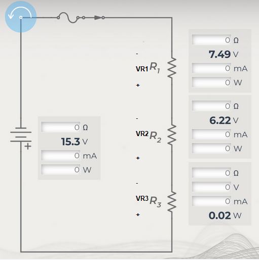
Transcribed Image Text:In the provided circuit diagram, we can observe a series circuit composed of a power source and three resistors labeled \( R_1 \), \( R_2 \), and \( R_3 \). Below are details of the measurements at different points in the circuit:
**Power Source:**
- Voltage: \( 15.3 \, \text{V} \)
- Current: \( 0 \, \text{mA} \) (not measured)
- Power: \( 0 \, \text{W} \) (not measured)
**Resistor \( R_1 \):**
- Voltage Drop: \( 7.49 \, \text{V} \)
- Current: \( 0 \, \text{mA} \) (not measured)
- Power: \( 0 \, \text{W} \) (not measured)
**Resistor \( R_2 \):**
- Voltage Drop: \( 6.22 \, \text{V} \)
- Current: \( 0 \, \text{mA} \) (not measured)
- Power: \( 0 \, \text{W} \) (not measured)
**Resistor \( R_3 \):**
- Voltage Drop: \( 0 \, \text{V} \) (not measured)
- Current: \( 0 \, \text{mA} \) (not measured)
- Power: \( 0.02 \, \text{W} \)
### Explanation:
- The circuit begins with a switch, positioned before the power source, indicating a potential closed circuit for current flow.
- There is an inductor present just after the switch that may initially resist changes in current.
- Following the power supply, we see resistors \( R_1 \), \( R_2 \), and \( R_3 \) arranged one after another in a vertical alignment, connected in series.
- Since this is a series circuit, the same current flows through all components, although in this case, current and power are shown as zero, possibly indicating that these values were not directly measured or are considered negligible for this visualization.
This detailed look at the circuit allows understanding and analysis of voltage distribution across each resistor, with the provided voltage and power readings being pivotal in determining the electrical characteristics of the circuit devices involved.
Expert Solution
Step 1: Question analysis:
Calculate the voltage current and power of each element.
In the given circuit i defined everything. Now let us calculate one by one.

Trending now
This is a popular solution!

Step by step
Solved in 3 steps with 3 images

Knowledge Booster


Learn more about
Need a deep-dive on the concept behind this application? Look no further. Learn more about this topic, electrical-engineering and related others by exploring similar questions and additional content below.Recommended textbooks for you
Introductory Circuit Analysis (13th Edition)
Electrical Engineering
ISBN:
9780133923605
Author:
Robert L. Boylestad
Publisher:
PEARSON

Delmar's Standard Textbook Of Electricity
Electrical Engineering
ISBN:
9781337900348
Author:
Stephen L. Herman
Publisher:
Cengage Learning

Programmable Logic Controllers
Electrical Engineering
ISBN:
9780073373843
Author:
Frank D. Petruzella
Publisher:
McGraw-Hill Education
Introductory Circuit Analysis (13th Edition)
Electrical Engineering
ISBN:
9780133923605
Author:
Robert L. Boylestad
Publisher:
PEARSON
Delmar's Standard Textbook Of Electricity
Electrical Engineering
ISBN:
9781337900348
Author:
Stephen L. Herman
Publisher:
Cengage Learning
Programmable Logic Controllers
Electrical Engineering
ISBN:
9780073373843
Author:
Frank D. Petruzella
Publisher:
McGraw-Hill Education

Fundamentals of Electric Circuits
Electrical Engineering
ISBN:
9780078028229
Author:
Charles K Alexander, Matthew Sadiku
Publisher:
McGraw-Hill Education

Electric Circuits. (11th Edition)
Electrical Engineering
ISBN:
9780134746968
Author:
James W. Nilsson, Susan Riedel
Publisher:
PEARSON

Engineering Electromagnetics
Electrical Engineering
ISBN:
9780078028151
Author:
Hayt, William H. (william Hart), Jr, BUCK, John A.
Publisher:
Mcgraw-hill Education,