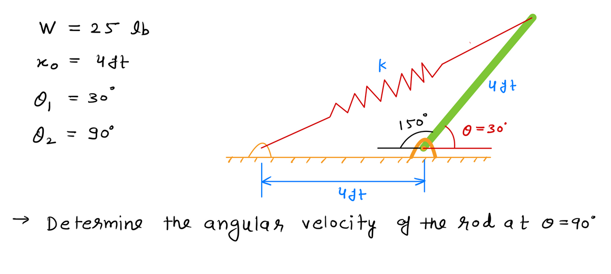
C Part A If the rod is released from rest when 0-30°, determine the angular velocity of the rod the instant the spring becomes unstretched. Express your answer to three significant figures and include the appropriate units. Enter positive value if the angular velocity is counterclockwise and negative value if the angular velocity is clockwise. HA rad ?
C Part A If the rod is released from rest when 0-30°, determine the angular velocity of the rod the instant the spring becomes unstretched. Express your answer to three significant figures and include the appropriate units. Enter positive value if the angular velocity is counterclockwise and negative value if the angular velocity is clockwise. HA rad ?
Elements Of Electromagnetics
7th Edition
ISBN:9780190698614
Author:Sadiku, Matthew N. O.
Publisher:Sadiku, Matthew N. O.
ChapterMA: Math Assessment
Section: Chapter Questions
Problem 1.1MA
Related questions
Question
![**Educational Content Transcription: Physics Problem Example**
---
**Problem Statement:**
The 25 lb slender rod \( AB \) is attached to spring \( BC \) which has an unstretched length of 4 ft. [Refer to Figure 1]
**Part A:**
If the rod is released from rest when \( \theta = 30^\circ \), determine the angular velocity of the rod at the instant the spring becomes unstretched.
**Instructions:**
Express your answer to three significant figures and include the appropriate units. Enter a positive value if the angular velocity is counterclockwise and a negative value if the angular velocity is clockwise.
**Solution Submission:**
- Input Box for Angular Velocity, \( \omega = 1.18 \, \text{rad/s} \)
**Feedback:**
- You have already submitted this answer. Enter a new answer. No credit lost. Try again.
**Interface:**
- Options to Submit, View Previous Answers, and Request Answer are available.
---
*Note: The image referenced as Figure 1 is not displayed here, but it would typically show the initial setup of the rod and spring for better visualization.*
---
This educational content is designed to help students engage with problem-solving related to rotational dynamics and spring mechanics.](/v2/_next/image?url=https%3A%2F%2Fcontent.bartleby.com%2Fqna-images%2Fquestion%2Fc77f544a-ee3e-4902-8958-66e53c68e4a2%2F7c9ff519-3008-4e82-a906-00f1ed7446cd%2F361wjm_processed.jpeg&w=3840&q=75)
Transcribed Image Text:**Educational Content Transcription: Physics Problem Example**
---
**Problem Statement:**
The 25 lb slender rod \( AB \) is attached to spring \( BC \) which has an unstretched length of 4 ft. [Refer to Figure 1]
**Part A:**
If the rod is released from rest when \( \theta = 30^\circ \), determine the angular velocity of the rod at the instant the spring becomes unstretched.
**Instructions:**
Express your answer to three significant figures and include the appropriate units. Enter a positive value if the angular velocity is counterclockwise and a negative value if the angular velocity is clockwise.
**Solution Submission:**
- Input Box for Angular Velocity, \( \omega = 1.18 \, \text{rad/s} \)
**Feedback:**
- You have already submitted this answer. Enter a new answer. No credit lost. Try again.
**Interface:**
- Options to Submit, View Previous Answers, and Request Answer are available.
---
*Note: The image referenced as Figure 1 is not displayed here, but it would typically show the initial setup of the rod and spring for better visualization.*
---
This educational content is designed to help students engage with problem-solving related to rotational dynamics and spring mechanics.

Transcribed Image Text:The diagram illustrates a mechanical system involving a spring and a lever. Here is a detailed explanation of the components and the setup:
1. **Components**:
- **Spring**: The spring is labeled with a spring constant \( k = 5 \, \text{lb/ft} \).
- **Lever**: The lever AB has a length of 4 feet and is anchored at point A on the ground. It can rotate about point A.
- **Angle**: The lever forms an angle \( \theta \) with the horizontal surface.
2. **Configuration**:
- The spring is connected between two points: one end of the spring is attached to point C on the horizontal surface, 4 feet away from point A. The other end is connected to the lever at point B.
- The horizontal distance between points A and C is given as 4 feet.
This setup typically models a mechanical system where the spring force influences the movement or rotation of the lever. Understanding such systems is essential in engineering applications for designing mechanisms that rely on spring-loaded components.
Expert Solution
Step 1: Given data

Step by step
Solved in 3 steps with 3 images

Knowledge Booster
Learn more about
Need a deep-dive on the concept behind this application? Look no further. Learn more about this topic, mechanical-engineering and related others by exploring similar questions and additional content below.Recommended textbooks for you

Elements Of Electromagnetics
Mechanical Engineering
ISBN:
9780190698614
Author:
Sadiku, Matthew N. O.
Publisher:
Oxford University Press

Mechanics of Materials (10th Edition)
Mechanical Engineering
ISBN:
9780134319650
Author:
Russell C. Hibbeler
Publisher:
PEARSON

Thermodynamics: An Engineering Approach
Mechanical Engineering
ISBN:
9781259822674
Author:
Yunus A. Cengel Dr., Michael A. Boles
Publisher:
McGraw-Hill Education

Elements Of Electromagnetics
Mechanical Engineering
ISBN:
9780190698614
Author:
Sadiku, Matthew N. O.
Publisher:
Oxford University Press

Mechanics of Materials (10th Edition)
Mechanical Engineering
ISBN:
9780134319650
Author:
Russell C. Hibbeler
Publisher:
PEARSON

Thermodynamics: An Engineering Approach
Mechanical Engineering
ISBN:
9781259822674
Author:
Yunus A. Cengel Dr., Michael A. Boles
Publisher:
McGraw-Hill Education

Control Systems Engineering
Mechanical Engineering
ISBN:
9781118170519
Author:
Norman S. Nise
Publisher:
WILEY

Mechanics of Materials (MindTap Course List)
Mechanical Engineering
ISBN:
9781337093347
Author:
Barry J. Goodno, James M. Gere
Publisher:
Cengage Learning

Engineering Mechanics: Statics
Mechanical Engineering
ISBN:
9781118807330
Author:
James L. Meriam, L. G. Kraige, J. N. Bolton
Publisher:
WILEY