(c) Calculate the torques produced by and F4, including the sign of the torque indicating the sense of rotation, positive for counter-clockwise rotation and negative clockwise rotation. Help: When using the formula for torque, the angle is between the tails of which two vectors? Draw a diagram showing the vectors and to figure out the angle to be used in the calculations of torque. Enter to 3 significant figures TF3 TFA = = HBetween 5. and which force produces therger or Pis TF2 (e) Calculate the torque produced by F2, including the sign of the torque indicating the sense of rotation - positive for counter-clockwise rotation and negative clockwise rotation. Enter to 3 significant figures = = 1,F3 Nm Nm (f) Calculate the moment arms of F3 and F4. Note: Moment arms are distances and positive. Enter to 3 significant figures ₁,FA = Nm m m
Rigid Body
A rigid body is an object which does not change its shape or undergo any significant deformation due to an external force or movement. Mathematically speaking, the distance between any two points inside the body doesn't change in any situation.
Rigid Body Dynamics
Rigid bodies are defined as inelastic shapes with negligible deformation, giving them an unchanging center of mass. It is also generally assumed that the mass of a rigid body is uniformly distributed. This property of rigid bodies comes in handy when we deal with concepts like momentum, angular momentum, force and torque. The study of these properties – viz., force, torque, momentum, and angular momentum – of a rigid body, is collectively known as rigid body dynamics (RBD).
![### Torque and Moment Arm Calculations
#### (c) Calculating Torques for \( F_3 \) and \( F_4 \)
Calculate the torques produced by \( F_3 \) and \( F_4 \), including the sign of the torque to indicate the sense of rotation: *positive for counter-clockwise rotation* and *negative for clockwise rotation*.
**Help:** When using the formula for torque, consider the angle between the tails of the two vectors involved. Draw a diagram showing the vectors \( \vec{r} \) and \( \vec{F} \) to figure out the angle to use in torque calculations.
- **Enter to 3 significant figures**
\( \tau_{F_3} = \) \(\_\_\_\) Nm
\( \tau_{F_4} = \) \(\_\_\_\) Nm
*(Note: Between \( F_3 \) and \( F_4 \), selection for the larger torque is crossed out with a black scribble.)*
#### (e) Calculating Torque for \( F_2 \)
Calculate the torque produced by \( F_2 \), specifying the sign for rotation: *positive for counter-clockwise rotation* and *negative for clockwise rotation*.
- **Enter to 3 significant figures**
\( \tau_{F_2} = \) \(\_\_\_\) Nm
#### (f) Calculating Moment Arms for \( F_3 \) and \( F_4 \)
Calculate the moment arms for \( F_3 \) and \( F_4 \). Note that moment arms are distances and always positive.
- **Enter to 3 significant figures**
\( r_{\perp, F_3} = \) \(\_\_\_\) m
\( r_{\perp, F_4} = \) \(\_\_\_\) m](/v2/_next/image?url=https%3A%2F%2Fcontent.bartleby.com%2Fqna-images%2Fquestion%2F5a3df371-d475-482a-84ce-057c931f1fc6%2F540796e5-8ac4-49cb-869a-10255d173ffd%2Fu4cq5hv_processed.png&w=3840&q=75)
![**Title: Torque and Rotation Analysis of a Meter Rule**
A meter rule is anchored at the point O and is free to rotate about an axis passing through O, perpendicular to the plane of the meter rule. Forces \( F_1, F_2, F_3, F_4, \) and \( F_5 \), of equal magnitudes, act on the ruler at different locations. The magnitude of each force is 25.0 N and \( \theta = 30^\circ \). The distances along the ruler are given in cm. Assume all quantities are correct to 3 significant figures.
**Diagram Explanation:**
1. **Anchor Point (O):** The meter rule is anchored at point O, allowing it to rotate.
2. **Forces:**
- \( F_1 \) is acting vertically downward at 0 cm.
- \( F_2 \) is acting at 30 cm, forming a \( 30^\circ \) angle with the vertical.
- \( F_3 \) is acting vertically downward at 60 cm.
- \( F_4 \) is acting at 60 cm, forming a \( 30^\circ \) angle with the vertical.
- \( F_5 \) is acting horizontally to the right at 100 cm.
3. **Tasks:**
- **(a)** Determine whether each force can or cannot rotate the ruler and select the correct rationale.
- **(b)** Identify which force between \( F_2 \) or \( F_4 \) produces a larger torque.
- **(c)** Calculate the torques produced by \( F_3 \) and \( F_4 \), including the sign of the torque indicating the sense of rotation: positive for counter-clockwise rotation and negative for clockwise rotation. A hint is provided regarding the angle between two vectors.
- **(d)** Determine which force between \( F_2 \) and \( F_4 \) produces the larger torque.
**Interactive Elements:**
- Dropdown menus to select the rationale for each force's ability to rotate the ruler.
- Input fields for calculated torques (\( T_{F_3} \) and \( T_{F_4} \)) to three significant figures.
This exercise helps understand the concepts of torque and rotational equilibrium by analyzing the forces and angles involved.](/v2/_next/image?url=https%3A%2F%2Fcontent.bartleby.com%2Fqna-images%2Fquestion%2F5a3df371-d475-482a-84ce-057c931f1fc6%2F540796e5-8ac4-49cb-869a-10255d173ffd%2F1uqlq0r_processed.png&w=3840&q=75)
![](/static/compass_v2/shared-icons/check-mark.png)
Trending now
This is a popular solution!
Step by step
Solved in 4 steps with 15 images
![Blurred answer](/static/compass_v2/solution-images/blurred-answer.jpg)
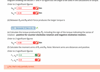
![Certainly! Below is the transcription of the image for an educational website:
---
**Torque and Moment Arm Calculations**
- **Torque Values:**
- \( \tau_{F_3} = -10.8 \, \text{Nm} \) ❌
- \( \tau_{F_4} = -9.35 \, \text{Nm} \) ❌
- **Question (d):** Between \( F_2 \) and \( F_4 \), which force produces the larger torque?
- **Answer:** \( F_4 \) - because it has a larger moment arm. ✅
- **Torque Calculation for \( F_2 \):** Include the sign of the torque indicating the sense of rotation:
- Positive for counter-clockwise rotation and negative for clockwise rotation.
- \( \tau_{F_2} = -4.68 \, \text{Nm} \) ❌
- **Moment Arm Calculations:**
- \( r_{\perp, F_3} = 0.6 \, \text{m} \) ✅
- \( r_{\perp, F_4} = 0.6 \, \text{m} \) ❌
- **Feedback:**
- No, that's only partially correct.
---
**Graph/Diagram Explanation:**
The image seems to involve entries related to torque and moment arms, with specific focus on calculating these values for different forces. An indication of correctness or incorrectness is provided for each calculation, likely based on a comparison with expected values.](https://content.bartleby.com/qna-images/question/5a3df371-d475-482a-84ce-057c931f1fc6/386734a6-7993-40de-8203-3de976b654db/sbjg9h9_thumbnail.png)
![College Physics](https://www.bartleby.com/isbn_cover_images/9781305952300/9781305952300_smallCoverImage.gif)
![University Physics (14th Edition)](https://www.bartleby.com/isbn_cover_images/9780133969290/9780133969290_smallCoverImage.gif)
![Introduction To Quantum Mechanics](https://www.bartleby.com/isbn_cover_images/9781107189638/9781107189638_smallCoverImage.jpg)
![Physics for Scientists and Engineers](https://www.bartleby.com/isbn_cover_images/9781337553278/9781337553278_smallCoverImage.gif)
![Lecture- Tutorials for Introductory Astronomy](https://www.bartleby.com/isbn_cover_images/9780321820464/9780321820464_smallCoverImage.gif)
![College Physics: A Strategic Approach (4th Editio…](https://www.bartleby.com/isbn_cover_images/9780134609034/9780134609034_smallCoverImage.gif)