Bo Determine the inductance at terminals A B in the network shown above. Take the inductor values to be L1 = 2mH, L2 = 8mH,L3 = 4mH, L4 = 1mH,L, = 9mH, L6 = 5mH and L7 = 4mH. Redraw the schematic after combining parallel or series inductors. LAB = 9, mH
Bo Determine the inductance at terminals A B in the network shown above. Take the inductor values to be L1 = 2mH, L2 = 8mH,L3 = 4mH, L4 = 1mH,L, = 9mH, L6 = 5mH and L7 = 4mH. Redraw the schematic after combining parallel or series inductors. LAB = 9, mH

Introductory Circuit Analysis (13th Edition)
13th Edition
ISBN:9780133923605
Author:Robert L. Boylestad
Publisher:Robert L. Boylestad
Chapter1: Introduction
Section: Chapter Questions
Problem 1P: Visit your local library (at school or home) and describe the extent to which it provides literature...

Related questions
Question
![**Image Description for Educational Website:**
**Diagram Explanation:**
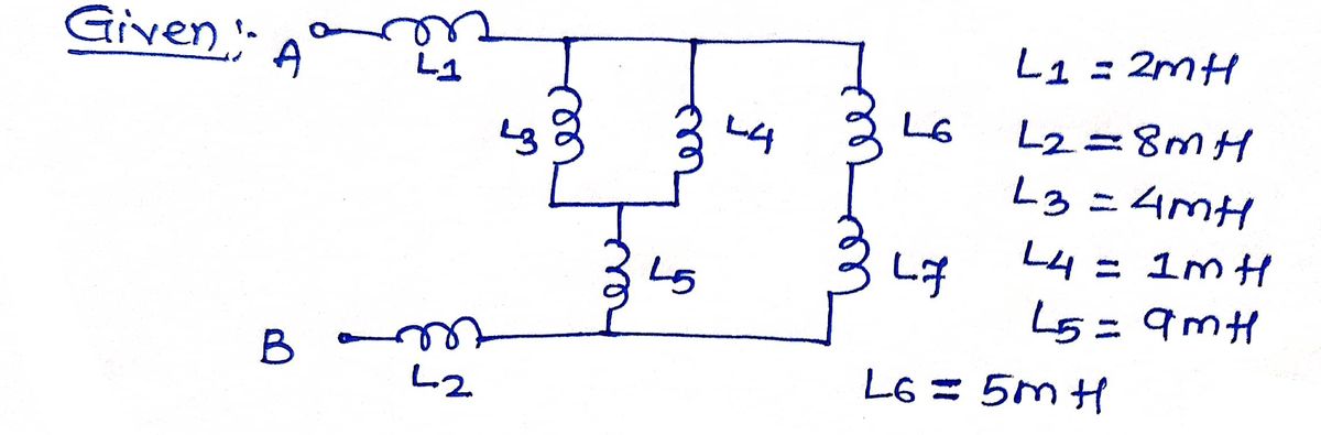
The diagram displays an electrical network consisting of six inductors labeled \( L_1 \) through \( L_6 \). These inductors are connected in various combinations of series and parallel circuits across two terminals, labeled \( A \) and \( B \).
1. **Inductor Configuration:**
- \( L_1 \) and \( L_2 \) are connected in series between terminals \( A \) and \( B \).
- \( L_3 \) and \( L_4 \) are connected in parallel.
- \( L_5 \) and \( L_6 \) are also connected in parallel.
- The parallel arrangement of \( L_3 \) and \( L_4 \) is in series with the parallel arrangement of \( L_5 \) and \( L_6 \).
2. **Overall Network:**
- \( L_1 \) and \( L_2 \) in series are connected in parallel with the entire series arrangement of the parallel combinations.
**Text Instructions:**
Determine the inductance at terminals \( A - B \) in the network shown above. Take the inductor values to be \( L_1 = 2 \, \text{mH}, L_2 = 8 \, \text{mH}, L_3 = 4 \, \text{mH}, L_4 = 1 \, \text{mH}, L_5 = 9 \, \text{mH}, L_6 = 5 \, \text{mH} \) and \( L_T = 4 \, \text{mH} \). Redraw the schematic after combining parallel or series inductors.
\[ L_{AB} = \boxed{} \, \text{mH} \]](/v2/_next/image?url=https%3A%2F%2Fcontent.bartleby.com%2Fqna-images%2Fquestion%2F0c42d3d3-c669-4ebd-a92e-b9a728000a05%2Fd892bcf7-b0c9-4c30-8a66-eb7d522a79d1%2F89yzsd_processed.png&w=3840&q=75)
Transcribed Image Text:**Image Description for Educational Website:**
**Diagram Explanation:**
The diagram displays an electrical network consisting of six inductors labeled \( L_1 \) through \( L_6 \). These inductors are connected in various combinations of series and parallel circuits across two terminals, labeled \( A \) and \( B \).
1. **Inductor Configuration:**
- \( L_1 \) and \( L_2 \) are connected in series between terminals \( A \) and \( B \).
- \( L_3 \) and \( L_4 \) are connected in parallel.
- \( L_5 \) and \( L_6 \) are also connected in parallel.
- The parallel arrangement of \( L_3 \) and \( L_4 \) is in series with the parallel arrangement of \( L_5 \) and \( L_6 \).
2. **Overall Network:**
- \( L_1 \) and \( L_2 \) in series are connected in parallel with the entire series arrangement of the parallel combinations.
**Text Instructions:**
Determine the inductance at terminals \( A - B \) in the network shown above. Take the inductor values to be \( L_1 = 2 \, \text{mH}, L_2 = 8 \, \text{mH}, L_3 = 4 \, \text{mH}, L_4 = 1 \, \text{mH}, L_5 = 9 \, \text{mH}, L_6 = 5 \, \text{mH} \) and \( L_T = 4 \, \text{mH} \). Redraw the schematic after combining parallel or series inductors.
\[ L_{AB} = \boxed{} \, \text{mH} \]
Expert Solution
Step 1

Step by step
Solved in 2 steps with 2 images

Knowledge Booster


Learn more about
Need a deep-dive on the concept behind this application? Look no further. Learn more about this topic, electrical-engineering and related others by exploring similar questions and additional content below.Recommended textbooks for you
Introductory Circuit Analysis (13th Edition)
Electrical Engineering
ISBN:
9780133923605
Author:
Robert L. Boylestad
Publisher:
PEARSON

Delmar's Standard Textbook Of Electricity
Electrical Engineering
ISBN:
9781337900348
Author:
Stephen L. Herman
Publisher:
Cengage Learning

Programmable Logic Controllers
Electrical Engineering
ISBN:
9780073373843
Author:
Frank D. Petruzella
Publisher:
McGraw-Hill Education
Introductory Circuit Analysis (13th Edition)
Electrical Engineering
ISBN:
9780133923605
Author:
Robert L. Boylestad
Publisher:
PEARSON
Delmar's Standard Textbook Of Electricity
Electrical Engineering
ISBN:
9781337900348
Author:
Stephen L. Herman
Publisher:
Cengage Learning
Programmable Logic Controllers
Electrical Engineering
ISBN:
9780073373843
Author:
Frank D. Petruzella
Publisher:
McGraw-Hill Education

Fundamentals of Electric Circuits
Electrical Engineering
ISBN:
9780078028229
Author:
Charles K Alexander, Matthew Sadiku
Publisher:
McGraw-Hill Education

Electric Circuits. (11th Edition)
Electrical Engineering
ISBN:
9780134746968
Author:
James W. Nilsson, Susan Riedel
Publisher:
PEARSON

Engineering Electromagnetics
Electrical Engineering
ISBN:
9780078028151
Author:
Hayt, William H. (william Hart), Jr, BUCK, John A.
Publisher:
Mcgraw-hill Education,