Block A (m = 3 kg) and Block B (m = 5 kg) seen in the figure at right are attached to a pulley system that is released from rest. What will the velocity of Block B be when t = 6s?
Block A (m = 3 kg) and Block B (m = 5 kg) seen in the figure at right are attached to a pulley system that is released from rest. What will the velocity of Block B be when t = 6s?

College Physics
11th Edition
ISBN:9781305952300
Author:Raymond A. Serway, Chris Vuille
Publisher:Raymond A. Serway, Chris Vuille
Chapter1: Units, Trigonometry. And Vectors
Section: Chapter Questions
Problem 1CQ: Estimate the order of magnitude of the length, in meters, of each of the following; (a) a mouse, (b)...

Related questions

Topic Video
Question
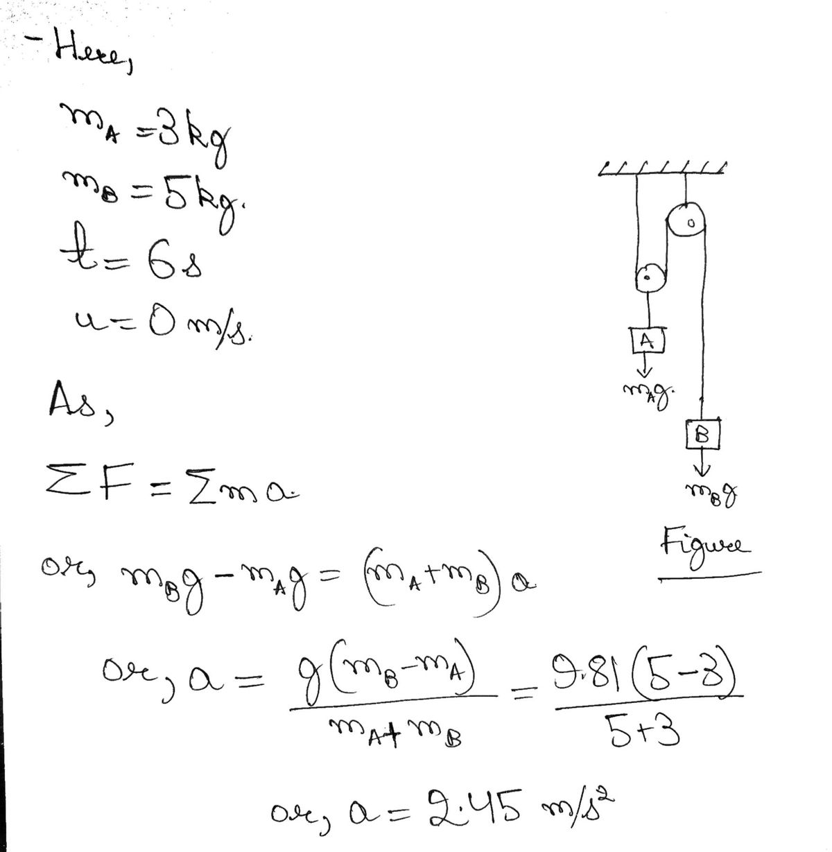
Block A (m = 3 kg) and Block B (m = 5 kg) seen in the figure at right are attached to a pulley system that is released from rest. What will the velocity of Block B be when t = 6s?

Transcribed Image Text:The image depicts a mechanical system involving pulleys and weights, often used to demonstrate principles of physics such as tension, force, and mechanical advantage.
### Diagram Explanation
- **Pulleys:**
- There are two main pulleys labeled as C and D arranged vertically.
- Pulley C is fixed to the ceiling structure, acting as a support.
- Pulley D hangs from the rope over Pulley C.
- **Weights:**
- Two weights labeled A and B are suspended in the system.
- Weight A is attached to a rope passing over Pulley D.
- Weight B is attached directly to the remaining part of the rope extending downward from Pulley D.
- **Ropes:**
- The rope that holds weight A passes over Pulley D, loops back upwards, and loops over Pulley C to support the system.
- The rope supporting weight B extends downward directly from Pulley D.
- **Measurement Points:**
- \( s_A \) is the vertical distance measured from a datum point to weight A.
- \( s_B \) is the vertical distance measured from the same datum point to weight B.
### Educational Context
This setup is often used in physics education to illustrate:
- **Mechanical Advantage:** Explains how pulleys can change the direction of forces and multiply force inputs to lift weights more easily.
- **Tension and Forces:** Demonstrates the distribution of tension across the ropes and its impact on the forces experienced by the weights.
- **Kinematics of Pulleys:** Involves studying how the movements of weights A and B are related, considering the fixed lengths of ropes involved.
This arrangement allows for discussion on topics like:
- Calculating forces in each rope segment.
- Analyzing the balance of forces for equilibrium.
- Exploring the relationship between distances \( s_A \) and \( s_B \) when the system is in motion.
This diagram is useful for student experiments and problem-solving exercises in physics classes.
Expert Solution
Step 1 : Basics

Step by step
Solved in 2 steps with 2 images

Knowledge Booster


Learn more about
Need a deep-dive on the concept behind this application? Look no further. Learn more about this topic, physics and related others by exploring similar questions and additional content below.Recommended textbooks for you
College Physics
Physics
ISBN:
9781305952300
Author:
Raymond A. Serway, Chris Vuille
Publisher:
Cengage Learning

University Physics (14th Edition)
Physics
ISBN:
9780133969290
Author:
Hugh D. Young, Roger A. Freedman
Publisher:
PEARSON

Introduction To Quantum Mechanics
Physics
ISBN:
9781107189638
Author:
Griffiths, David J., Schroeter, Darrell F.
Publisher:
Cambridge University Press
College Physics
Physics
ISBN:
9781305952300
Author:
Raymond A. Serway, Chris Vuille
Publisher:
Cengage Learning
University Physics (14th Edition)
Physics
ISBN:
9780133969290
Author:
Hugh D. Young, Roger A. Freedman
Publisher:
PEARSON
Introduction To Quantum Mechanics
Physics
ISBN:
9781107189638
Author:
Griffiths, David J., Schroeter, Darrell F.
Publisher:
Cambridge University Press

Physics for Scientists and Engineers
Physics
ISBN:
9781337553278
Author:
Raymond A. Serway, John W. Jewett
Publisher:
Cengage Learning

Lecture- Tutorials for Introductory Astronomy
Physics
ISBN:
9780321820464
Author:
Edward E. Prather, Tim P. Slater, Jeff P. Adams, Gina Brissenden
Publisher:
Addison-Wesley

College Physics: A Strategic Approach (4th Editio…
Physics
ISBN:
9780134609034
Author:
Randall D. Knight (Professor Emeritus), Brian Jones, Stuart Field
Publisher:
PEARSON