An LTI system is defined by the equation d*y(t) +4 ¢y() + 4y(t) = dx(e) + 0.5x(t) dt dt dt (a) Find the characteristic equation, characteristic roots and characteristic modes of this system (b) Comment on the stability of the system. (c) Find y.(t), the zero-input component of the response fort 2 0, if the initial conditions are y. (0-) = 3 and y,(0 -) = -4
An LTI system is defined by the equation d*y(t) +4 ¢y() + 4y(t) = dx(e) + 0.5x(t) dt dt dt (a) Find the characteristic equation, characteristic roots and characteristic modes of this system (b) Comment on the stability of the system. (c) Find y.(t), the zero-input component of the response fort 2 0, if the initial conditions are y. (0-) = 3 and y,(0 -) = -4

Introductory Circuit Analysis (13th Edition)
13th Edition
ISBN:9780133923605
Author:Robert L. Boylestad
Publisher:Robert L. Boylestad
Chapter1: Introduction
Section: Chapter Questions
Problem 1P: Visit your local library (at school or home) and describe the extent to which it provides literature...

Related questions
Question

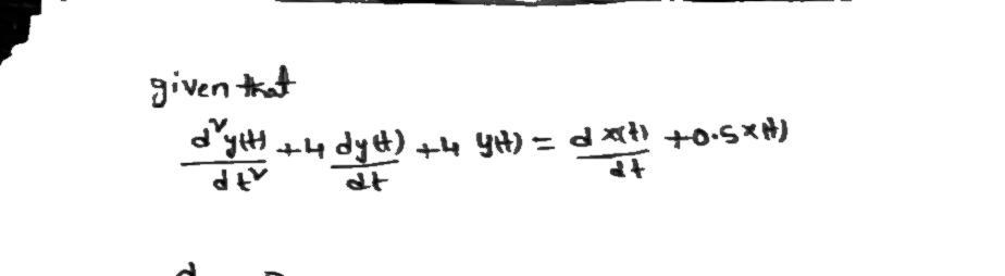
Transcribed Image Text:An LTI system is defined by the equation
d?y(t)
+ 4 dy(t) + 4y(t) = dx(t) + 0.5x(t)
dt
dt
(a) Find the characteristic equation, characteristic roots and characteristic modes of this
system
(b) Comment on the stability of the system.
(c) Find y.(t), the zero-input component of the response fort 2 0, if the initial conditions
are y. (0-) = 3 and yo(0 –) = -4
(d) Mathematically derive an expression for h(t), the impulse response of the system.
(e) Using the convolution tables and the result of part (d), find the zero-state output for the
system given the input x(t) = e-stu(t)
(f) What is the total system response based on the conditions and input specified above?
(g) What is the natural response and what is the forced response of this system?
(h) Using Matlab, plot the impulse and step responses and frequency response (magnitude
and phase) of this system directly from the differential equation.
Hint: Sample code given in Module 6 may be used, but frequency range will have to
be increased.
(1) Compare the impulse response plot from part (h) to the expression from part (d).
Comment on the overall shape and specific points on the plot that confirm that they are
equivalent.
G) Using the frequency response plots from part (h), determine the output of the system
if x(t) = 8+ 10 cos(t – 20°) + 6 cos(30t + 30°)
Hint: You can use the data cursor
feature to read the coordinate values off the
plots.
Expert Solution
Step 1
As per guidelines i have to answer first three sub parts . please post remaining again.

Step by step
Solved in 2 steps with 2 images

Recommended textbooks for you
Introductory Circuit Analysis (13th Edition)
Electrical Engineering
ISBN:
9780133923605
Author:
Robert L. Boylestad
Publisher:
PEARSON

Delmar's Standard Textbook Of Electricity
Electrical Engineering
ISBN:
9781337900348
Author:
Stephen L. Herman
Publisher:
Cengage Learning

Programmable Logic Controllers
Electrical Engineering
ISBN:
9780073373843
Author:
Frank D. Petruzella
Publisher:
McGraw-Hill Education
Introductory Circuit Analysis (13th Edition)
Electrical Engineering
ISBN:
9780133923605
Author:
Robert L. Boylestad
Publisher:
PEARSON
Delmar's Standard Textbook Of Electricity
Electrical Engineering
ISBN:
9781337900348
Author:
Stephen L. Herman
Publisher:
Cengage Learning
Programmable Logic Controllers
Electrical Engineering
ISBN:
9780073373843
Author:
Frank D. Petruzella
Publisher:
McGraw-Hill Education

Fundamentals of Electric Circuits
Electrical Engineering
ISBN:
9780078028229
Author:
Charles K Alexander, Matthew Sadiku
Publisher:
McGraw-Hill Education

Electric Circuits. (11th Edition)
Electrical Engineering
ISBN:
9780134746968
Author:
James W. Nilsson, Susan Riedel
Publisher:
PEARSON

Engineering Electromagnetics
Electrical Engineering
ISBN:
9780078028151
Author:
Hayt, William H. (william Hart), Jr, BUCK, John A.
Publisher:
Mcgraw-hill Education,