All four light bulbs are identical. Rank the bulb brightness. 1 > 2 = 3 > 4 1 > 4 > 2 = 3 4 > 2 = 3 > 1 1 = 2 = 3 = 4 4 = 1 > 2 = 3 4 > 1 > 2 = 3
All four light bulbs are identical. Rank the bulb brightness. 1 > 2 = 3 > 4 1 > 4 > 2 = 3 4 > 2 = 3 > 1 1 = 2 = 3 = 4 4 = 1 > 2 = 3 4 > 1 > 2 = 3

Introductory Circuit Analysis (13th Edition)
13th Edition
ISBN:9780133923605
Author:Robert L. Boylestad
Publisher:Robert L. Boylestad
Chapter1: Introduction
Section: Chapter Questions
Problem 1P: Visit your local library (at school or home) and describe the extent to which it provides literature...

Related questions
Question
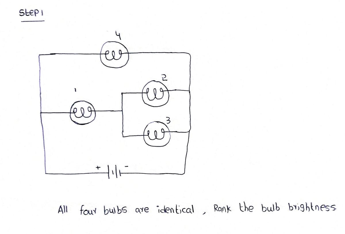
All four light bulbs are identical. Rank the bulb brightness.
|
1 > 2 = 3 > 4 |
||
|
1 > 4 > 2 = 3 |
||
|
4 > 2 = 3 > 1 |
||
|
1 = 2 = 3 = 4 |
||
|
4 = 1 > 2 = 3 |
||
|
4 > 1 > 2 = 3 |

Transcribed Image Text:The image depicts an electrical circuit consisting of four inductors and a power source. Here's a detailed breakdown:
### Components:
1. **Power Source:** Located at the bottom left corner, represented by two parallel lines, with the longer line indicating the positive terminal.
2. **Inductors:**
- **Inductor 1:** Situated to the right of the power source, directly connected in series.
- **Inductor 2 and Inductor 3:** Connected in parallel with each other, forming a parallel branch in the circuit.
- **Inductor 4:** Located at the top of the circuit, connected in series with Inductor 1 and the parallel combination of Inductor 2 and Inductor 3.
### Circuit Layout:
- The circuit is a closed loop, with Inductor 1 first in series with the power source.
- The parallel configuration of Inductor 2 and Inductor 3 follows, providing an alternate path for the current.
- Inductor 4 completes the loop, aligning in series with the rest of the components.
### Grid Background:
- The entire circuit is laid on a grid, likely for measurement or schematic purposes, ensuring precise component placement and connection paths.
This diagram is a typical example of a mixed configuration involving series and parallel inductors, useful in analyzing complex circuit behaviors such as resonance, impedance, and time constants in AC circuits.
Expert Solution
Step 1

Step by step
Solved in 2 steps with 2 images

Knowledge Booster


Learn more about
Need a deep-dive on the concept behind this application? Look no further. Learn more about this topic, electrical-engineering and related others by exploring similar questions and additional content below.Recommended textbooks for you
Introductory Circuit Analysis (13th Edition)
Electrical Engineering
ISBN:
9780133923605
Author:
Robert L. Boylestad
Publisher:
PEARSON

Delmar's Standard Textbook Of Electricity
Electrical Engineering
ISBN:
9781337900348
Author:
Stephen L. Herman
Publisher:
Cengage Learning

Programmable Logic Controllers
Electrical Engineering
ISBN:
9780073373843
Author:
Frank D. Petruzella
Publisher:
McGraw-Hill Education
Introductory Circuit Analysis (13th Edition)
Electrical Engineering
ISBN:
9780133923605
Author:
Robert L. Boylestad
Publisher:
PEARSON
Delmar's Standard Textbook Of Electricity
Electrical Engineering
ISBN:
9781337900348
Author:
Stephen L. Herman
Publisher:
Cengage Learning
Programmable Logic Controllers
Electrical Engineering
ISBN:
9780073373843
Author:
Frank D. Petruzella
Publisher:
McGraw-Hill Education

Fundamentals of Electric Circuits
Electrical Engineering
ISBN:
9780078028229
Author:
Charles K Alexander, Matthew Sadiku
Publisher:
McGraw-Hill Education

Electric Circuits. (11th Edition)
Electrical Engineering
ISBN:
9780134746968
Author:
James W. Nilsson, Susan Riedel
Publisher:
PEARSON

Engineering Electromagnetics
Electrical Engineering
ISBN:
9780078028151
Author:
Hayt, William H. (william Hart), Jr, BUCK, John A.
Publisher:
Mcgraw-hill Education,