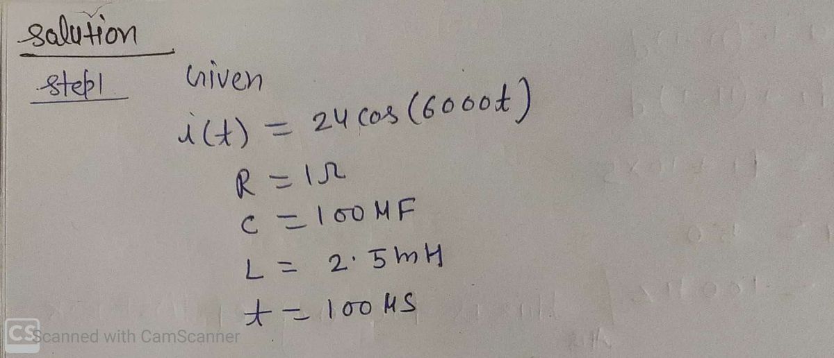
I have an RLC series circuit with i (t) = 24Cos (6000t). R = 10, C = 100 µF,L=2.5 mH. Find the voltage across R, C, and L at t = 100 us. Show your work %3D Edit Format Table 12pt v Paragraph v B
Q: Find the charge on the capacitor in an LRC- and i(0) = 0 A. (Round your answer to four 0.9154 хс…
A: Inductance, Resistance, Capacitance, Apllied…
Q: d help with #4
A: Solution. given the slope of the mass versus length is 0.865. And the measured length L and D is,…
Q: Fill in the table for this circuit. Show your work and then check your answer with PhET V R R1 R2 R3…
A: Three different resistor are given. We need to fill the table
Q: The emf phasor in (Figure 1) is shown at t = 12 ms. Assume E, = 12 V. Part B Figure < 1 of 1 What is…
A:
Q: For the RC Circuit shown find the charge on the capacitor at t=0.1 seconds after the switch is…
A:
Q: (Don't Forget Units!) 3. A. Resistors in Series- Parallel Source Voltage V_120 V (calculations)…
A:
Q: A low-pass RC filter has a crossover frequency fe = 300 Hz. Part A What is fe if the resistance R is…
A: For a Low pass filter Given the frequency constant, fc=300 Hz ωc=2πTcωc=2πfc =2π×300 =600 π…
Q: The circuit to the right consists of a battery (Vo = 3.00 V) and five resistors (R] = 411 Q, R2 =…
A:
Q: 22.0 ohm
A: Resistance (R1)=220ohm R2=100ohm R3=22ohm potential Vdc=5.0 volt Vtotal=Vdc=5.0 volt all…
Q: Please find attached image for questions.
A: I hope you find this helpful. If you have any question or clarification, do not hesitate to reach…
Q: The emf phasor in (Figure 1) is shown at t = 1.4 ms. Figure -50 V Eo 225° at t ✓ Correct Correct…
A: Part B: To determine the Peak value of emf we will use the Equation ε=ε∘cosωt the equation…
Q: 2. A. Resistors in Parallel (calculations) Source Voltage 24.0 V Equivalent Resistance Rp = Current…
A: Resistance is an electrical equipment that opposes the flow of current in a circuit. The resistances…
Q: Solve the series circuit below. Total 3 1 www 2{ V₁ = 24 V V₂ = 36 V V3 = V₁ = 1₁₂ = 1₂ = 13 = IT =…
A:
Q: Part A :20 Ω 5 Ω 2 Ω 4 Ω + ΞΑΙ What is the current through the 20 Ω resistor in (Figure 1) if the ΔV…
A: The resistors 20 Ω and 5 Ω are connected in parallel. 1Rp=120 Ω+15 ΩRp=4 Ω Calculate the equivalent…
Q: Help with the following question please answer on a piece of paper.
A:
Q: In this circuit find all missing components. Show your work Rs = 122 VT = 120 V ITERA SR₂=452 R₁ =…
A: Given:- A circuit is given as We see that the given voltage is V = 120 V and the resistance is…
Q: the current in the circuit is 3.3 µA
A: Initial capacitance, voltage and resistance are given and current after time t is also given. We…
Q: All parts needed
A:
Q: The bar shown has right angles and dimensions, L=35 cm by a by a and Part A Determine a. | ΑΣφ
A:
Q: The capacitor in the figure is initially uncharged. Immediately after the switch is closed, what is…
A: Immediately after switching on an RC circuit, the voltage across uncharged capacitors is zero since…
Q: The capacitor in the circuit shown below is initially uncharged. The switch is closed att 0 s.…
A:
Q: Can you help part A I need to show all work
A: (a) current in the left branch is from up to down and has a magnitude of 0.5A current in the middle…
Q: Correct Part B What is the current in the loop at t = 5.0us? Assume that only the circuit wire next…
A:
Q: 1) Most places you can plug devices into (walls in buildings, sockets in cars) are wired in parallel…
A: Parallel connection has following advantages over series are follows : Parallel circuit provide…
Q: 8. (FE practice!) The switch on the circuit below has been in position 1 for a long time before t=0,…
A: This is a question from the series R C circuit with DC power supply. In such circuit when we…
Q: Part A In the United States the standard voltage in homes is 120 V. Therefore, a "75 W" American…
A: Solution:- Resistance of the American bulb is R=(V2/P)R=(1202)/(75)R=192 Ohm
Q: 2. Calculate the resistance between points A and B in the circuit below. (100R = 100 N, 100u = 100…
A: In the given circuit, 100R=100Ω=100u=100μF=0.1mF200R=200Ω=200u=200μF=0.2mF 100Ω and 200Ω are in…
Q: In the circuit shown in the figure (Figure 1), the 6.0 N resistor is consuming energy at a rate of…
A:
Step by step
Solved in 2 steps with 3 images
- The capacitor in the circuit shown below is initially uncharged. The switch is closed at t = 0 s. AVbattery = 30 V, C = 3.0 F, and R = 2.0 Q. What is the current in the circuit at t = 7.5 s, in Ampere? Your answer needs to have 2 significant figures, including the negative sign in your answer if needed. Do not include the positive sign if the answer is positive. No unit is needed in your answer, it is already given in the question statement. R HIHreadable answer please thanks