a) By carefully observing the circuit, Find the between lok s,4KS2 and resistors loccated on side of the circuit given 'in Figurem equivalent resistance 12 KSR the right hand b) Redraw the circuit with the equivalent resistance and the rest of the Cincuit- C) APplying Kirchoffs current Law appropriate nodes find the current, lo
a) By carefully observing the circuit, Find the between lok s,4KS2 and resistors loccated on side of the circuit given 'in Figurem equivalent resistance 12 KSR the right hand b) Redraw the circuit with the equivalent resistance and the rest of the Cincuit- C) APplying Kirchoffs current Law appropriate nodes find the current, lo

Introductory Circuit Analysis (13th Edition)
13th Edition
ISBN:9780133923605
Author:Robert L. Boylestad
Publisher:Robert L. Boylestad
Chapter1: Introduction
Section: Chapter Questions
Problem 1P: Visit your local library (at school or home) and describe the extent to which it provides literature...

Related questions

Question

Transcribed Image Text:**Transcribed Educational Content:**
---
### Electrical Engineering Problem Set
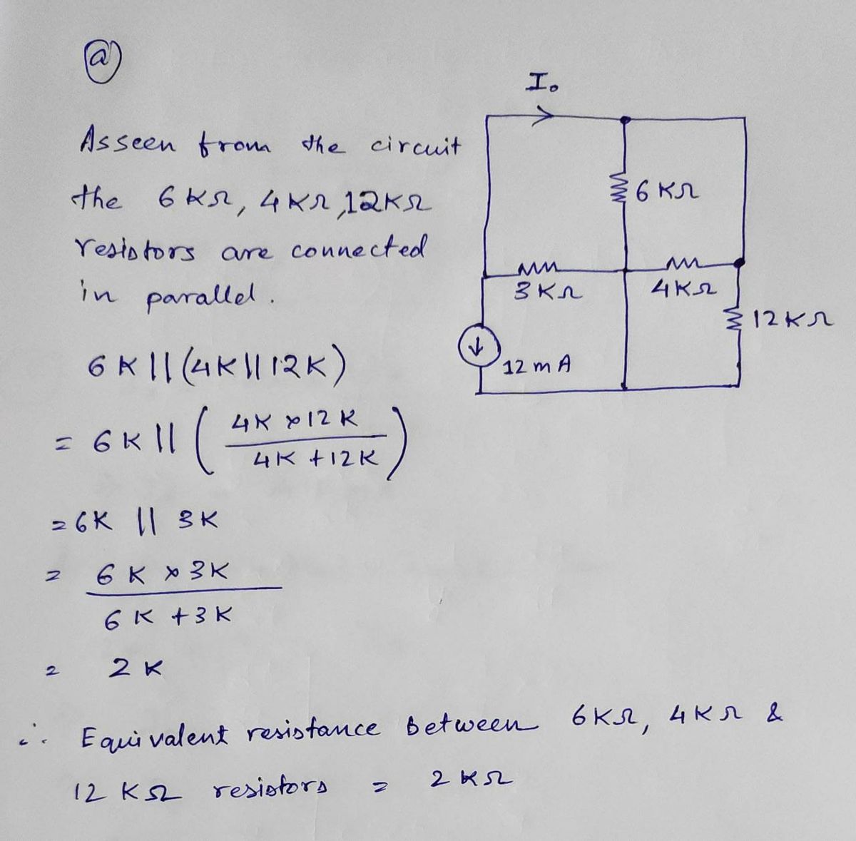
**a) By carefully observing the circuit, find the equivalent resistance between 6 kΩ, 4 kΩ, and 12 kΩ resistors located on the right-hand side of the circuit given in the figure.**
**b) Redraw the circuit with the equivalent resistance and the rest of the circuit.**
**c) Applying Kirchhoff's Current Law to appropriate nodes, find the current, I₀.**
**d) Using Kirchhoff's Voltage Law, find the voltage Vₓ given in the figure below.**
---
### Circuit Diagrams:
1. **First Circuit Diagram:**
- The circuit includes:
- A current source of 12 mA.
- Three resistors: 3 kΩ (left loop), 4 kΩ, and 12 kΩ (right loop).
- Note that the 6 kΩ resistor mentioned connects to the nodes adjoining the 4 kΩ and 12 kΩ resistors.
2. **Second Circuit Diagram:**
- The circuit includes:
- A voltage source indicated by Vₓ.
- A resistor of 8 kΩ.
- A dependent voltage source of Vₓ/4, oriented in the same loop as the 8 kΩ resistor.
---
**Instructions:**
1. Calculate the total equivalent resistance for the resistors in parallel on the right-hand side.
2. Redraw the circuit simplifying with the equivalent resistance.
3. Apply Kirchhoff's Current Law (KCL) to solve for the current I₀ at the nodes.
4. Apply Kirchhoff's Voltage Law (KVL) to solve for Vₓ in the voltage loop.
---
This exercise is designed to enhance understanding of circuit analysis through practical application of Kirchhoff's Laws.
Expert Solution
Step 1
According to company policy we are allowed to provide solution for only 3 sub parts of one question. If you require remaining parts please ask in a separate question.

Step by step
Solved in 2 steps with 2 images

Knowledge Booster


Learn more about
Need a deep-dive on the concept behind this application? Look no further. Learn more about this topic, electrical-engineering and related others by exploring similar questions and additional content below.Recommended textbooks for you
Introductory Circuit Analysis (13th Edition)
Electrical Engineering
ISBN:
9780133923605
Author:
Robert L. Boylestad
Publisher:
PEARSON

Delmar's Standard Textbook Of Electricity
Electrical Engineering
ISBN:
9781337900348
Author:
Stephen L. Herman
Publisher:
Cengage Learning

Programmable Logic Controllers
Electrical Engineering
ISBN:
9780073373843
Author:
Frank D. Petruzella
Publisher:
McGraw-Hill Education
Introductory Circuit Analysis (13th Edition)
Electrical Engineering
ISBN:
9780133923605
Author:
Robert L. Boylestad
Publisher:
PEARSON
Delmar's Standard Textbook Of Electricity
Electrical Engineering
ISBN:
9781337900348
Author:
Stephen L. Herman
Publisher:
Cengage Learning
Programmable Logic Controllers
Electrical Engineering
ISBN:
9780073373843
Author:
Frank D. Petruzella
Publisher:
McGraw-Hill Education

Fundamentals of Electric Circuits
Electrical Engineering
ISBN:
9780078028229
Author:
Charles K Alexander, Matthew Sadiku
Publisher:
McGraw-Hill Education

Electric Circuits. (11th Edition)
Electrical Engineering
ISBN:
9780134746968
Author:
James W. Nilsson, Susan Riedel
Publisher:
PEARSON

Engineering Electromagnetics
Electrical Engineering
ISBN:
9780078028151
Author:
Hayt, William H. (william Hart), Jr, BUCK, John A.
Publisher:
Mcgraw-hill Education,