A BJT amplifier circuit shown to the right. Vcc=10V, I=1mA, and VT 25 mV at 300K. e) de voltage Vc = f) gm = g) r₂ = h) re= = R₁ 15K 4K Cs W- Re R₂ 10K Re 5K 8=99 BAZAART
A BJT amplifier circuit shown to the right. Vcc=10V, I=1mA, and VT 25 mV at 300K. e) de voltage Vc = f) gm = g) r₂ = h) re= = R₁ 15K 4K Cs W- Re R₂ 10K Re 5K 8=99 BAZAART

Introductory Circuit Analysis (13th Edition)
13th Edition
ISBN:9780133923605
Author:Robert L. Boylestad
Publisher:Robert L. Boylestad
Chapter1: Introduction
Section: Chapter Questions
Problem 1P: Visit your local library (at school or home) and describe the extent to which it provides literature...

Related questions

Question
100%
Please solve will upvote immediately

Transcribed Image Text:### BJT Amplifier Circuit Analysis
**Description:**
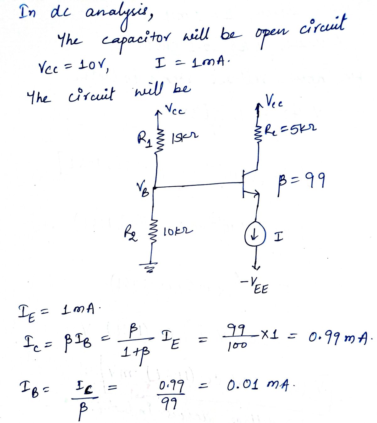
A BJT amplifier circuit is shown with a supply voltage \( V_{CC} = 10V \), a current \( I = 1mA \), and a thermal voltage \( V_T = 25mV \) at 300K.
**Circuit Diagram:**
- **Transistor Configuration:**
- The transistor is a Bipolar Junction Transistor with a current gain (\( \beta \)) of 99.
- Terminals are labeled as Emitter (E), Base (B), and Collector (C).
- **Components:**
- \( R_1 = 15k\Omega \) and \( R_2 = 10k\Omega \) form the voltage divider bias network.
- \( R_C = 5k\Omega \) is the collector resistor.
- \( R_L = 5k\Omega \) is the load resistor.
- \( R_S = 4k\Omega \) represents the source resistor.
- \( C_S \) and \( C_C \) are coupling capacitors, with the assumption that they act as shorts for AC signals.
- The voltage source is labeled as \( V_S \), and the output voltage is \( v_o \).
**Required Calculations:**
- **(e)** DC Voltage at the collector, \( V_C = \_\_\_\_\_\_\_\_ \)
- **(f)** Transconductance, \( g_m = \_\_\_\_\_\_\_\_ \)
- **(g)** Input resistance at the base, \( r_{\pi} = \_\_\_\_\_\_\_\_ \)
- **(h)** Emitter resistance, \( r_e = \_\_\_\_\_\_\_\_ \)
This content is intended for educational purposes, providing insights into the analysis and operational characteristics of a BJT amplifier circuit.
Expert Solution
Step 1

Step by step
Solved in 2 steps with 2 images

Knowledge Booster


Learn more about
Need a deep-dive on the concept behind this application? Look no further. Learn more about this topic, electrical-engineering and related others by exploring similar questions and additional content below.Recommended textbooks for you
Introductory Circuit Analysis (13th Edition)
Electrical Engineering
ISBN:
9780133923605
Author:
Robert L. Boylestad
Publisher:
PEARSON

Delmar's Standard Textbook Of Electricity
Electrical Engineering
ISBN:
9781337900348
Author:
Stephen L. Herman
Publisher:
Cengage Learning

Programmable Logic Controllers
Electrical Engineering
ISBN:
9780073373843
Author:
Frank D. Petruzella
Publisher:
McGraw-Hill Education
Introductory Circuit Analysis (13th Edition)
Electrical Engineering
ISBN:
9780133923605
Author:
Robert L. Boylestad
Publisher:
PEARSON
Delmar's Standard Textbook Of Electricity
Electrical Engineering
ISBN:
9781337900348
Author:
Stephen L. Herman
Publisher:
Cengage Learning
Programmable Logic Controllers
Electrical Engineering
ISBN:
9780073373843
Author:
Frank D. Petruzella
Publisher:
McGraw-Hill Education

Fundamentals of Electric Circuits
Electrical Engineering
ISBN:
9780078028229
Author:
Charles K Alexander, Matthew Sadiku
Publisher:
McGraw-Hill Education

Electric Circuits. (11th Edition)
Electrical Engineering
ISBN:
9780134746968
Author:
James W. Nilsson, Susan Riedel
Publisher:
PEARSON

Engineering Electromagnetics
Electrical Engineering
ISBN:
9780078028151
Author:
Hayt, William H. (william Hart), Jr, BUCK, John A.
Publisher:
Mcgraw-hill Education,