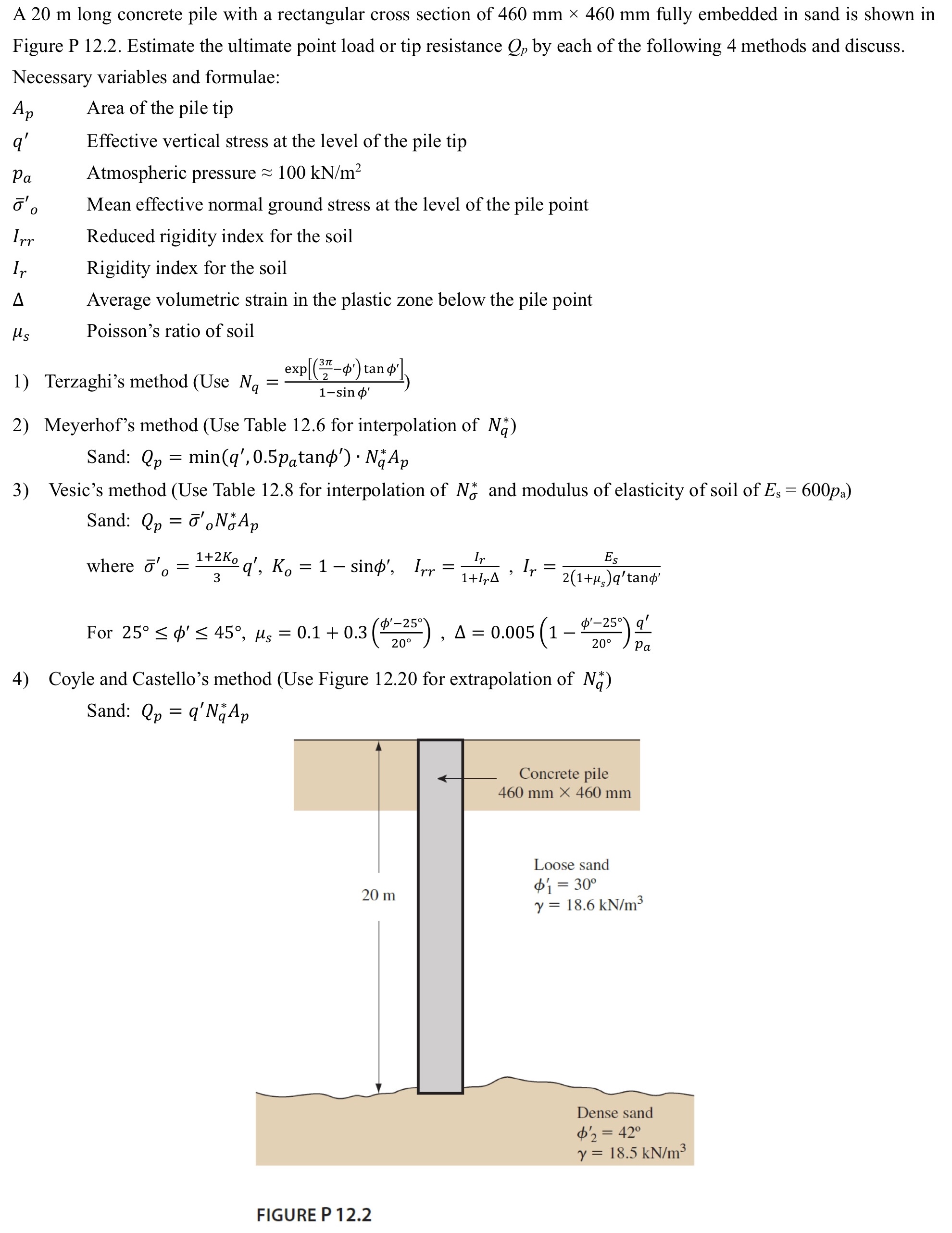
A 20 m long concrete pile with a rectangular cross section of 460 mm × 460 mm fully embedded in sand is shown in Figure P 12.2. Estimate the ultimate point load or tip resistance Qp by each of the following 4 methods and discuss. Necessary variables and formulae: Area of the pile tip Ap q' Pa o'o Irr Ir A μs Effective vertical stress at the level of the pile tip Atmospheric pressure 100 kN/m² Mean effective normal ground stress at the level of the pile point Reduced rigidity index for the soil Rigidity index for the soil Average volumetric strain in the plastic zone below the pile point Poisson's ratio of soil


I need detailed explanation to solve the exercise below. There are some formulas and hints, I also added some tables from the book.


Trending now
This is a popular solution!

Step by step
Solved in 3 steps with 2 images

I need detailed explanation to solve the exercise below. There are some formulas and hints, I also added some tables from the book.
Meyerhof's method, Coyle and Castello's method and Vesic's method were already solved.


I need detailed explanation to solve the exercise below. There are some formulas and hints, I also added some tables from the book.
Meyerhof's method, Coyle and Castello's method and Vesic's method were already solved.


I need detailed explanation to solve the exercise below. There are some formulas and hints, I also added some tables from the book.
Meyerhof's method, Coyle and Castello's method and Vesic's method were already solved.


I need detailed explanation to solve the exercise below. There are some formulas and hints, I also added some tables from the book.
Meyerhof's method, Coyle and Castello's method and Vesic's method were already solved.


I need detailed explanation to solve the exercise below. There are some formulas and hints, I also added some tables from the book.
Meyerhof's method, Coyle and Castello's method and Vesic's method were already solved.

I need detailed explanation to solve the exercise below. There are some formulas and hints, I also added some tables from the book.
Meyerhof's method, Coyle and Castello's method and Vesic's method were already solved.


I need detailed explanation to solve the exercise below. There are some formulas and hints, I also added some tables from the book.
Meyerhof's method, Coyle and Castello's method and Vesic's method were already solved.


I need detailed explanation to solve the exercise below. There are some formulas and hints, I also added some tables from the book.
Meyerhof's method, Coyle and Castello's method and Vesic's method were already solved.


I need detailed explanation to solve the exercise below. There are some formulas and hints, I also added some tables from the book.
Meyerhof's method, Coyle and Castello's method and Vesic's method were already solved.


I need detailed explanation to solve the exercise below. There are some formulas and hints, I also added some tables from the book.
Meyerhof's method, Coyle and Castello's method and Vesic's method were already solved.


