A 0 0 0 0 1 1 तातात 1 1 A B Cin B O 0 1 1 0 0 1 1 XOR CIN 0 1 0 1 0 1 0 1 G XOR AND AND H I OR Full Adder Truth Table G H I S Conte S COUT
A 0 0 0 0 1 1 तातात 1 1 A B Cin B O 0 1 1 0 0 1 1 XOR CIN 0 1 0 1 0 1 0 1 G XOR AND AND H I OR Full Adder Truth Table G H I S Conte S COUT

Introductory Circuit Analysis (13th Edition)
13th Edition
ISBN:9780133923605
Author:Robert L. Boylestad
Publisher:Robert L. Boylestad
Chapter1: Introduction
Section: Chapter Questions
Problem 1P: Visit your local library (at school or home) and describe the extent to which it provides literature...

Related questions
Question
Truth tables
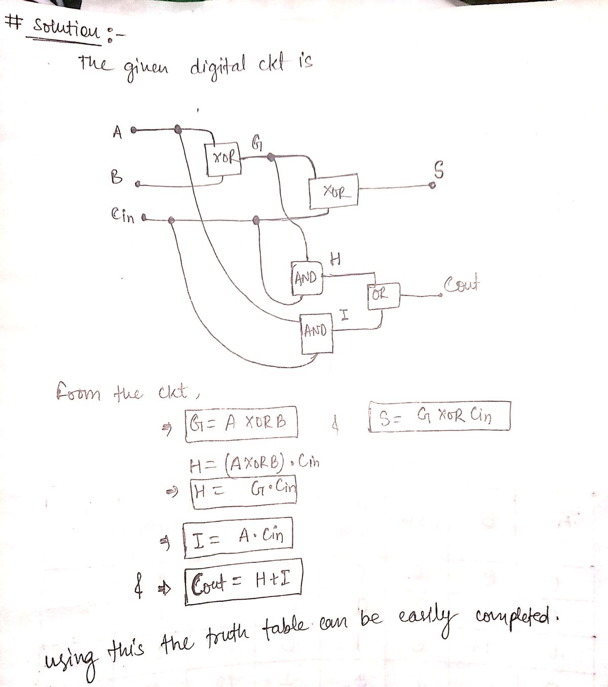
A full adder adds binary numbers and accounts for values carried in as well as out. A one-bit full-adder adds three one-bit numbers, often written as A, B, and Cin; A and B are the operands, and Cin is a bit carried in from the previous less-significant stage. Complete the full adder truth table using the AND, OR, XOR truth tables and the diagram.
|
Truth Tables |
||||||||
|
AND |
OR |
XOR |
||||||
|
A |
B |
AND |
A |
B |
OR |
A |
B |
XOR |
|
0 |
0 |
0 |
0 |
0 |
0 |
0 |
0 |
0 |
|
0 |
1 |
0 |
0 |
1 |
1 |
0 |
1 |
1 |
|
1 |
0 |
0 |
1 |
0 |
1 |
1 |
0 |
1 |
|
1 |
1 |
1 |
1 |
1 |
1 |
1 |
1 |
0 |
|
Full Adder Truth Table |
|||||||
|
A |
B |
CIN |
G |
H |
I |
S |
COUT |
|
0 |
0 |
0 |
|
|
|
|
|
|
0 |
0 |
1 |
|
|
|
|
|
|
0 |
1 |
0 |
|
|
|
|
|
|
0 |
1 |
1 |
|
|
|
|
|
|
1 |
0 |
0 |
|
|
|
|
|
|
1 |
0 |
1 |
|
|
|
|
|
|
1 |
1 |
0 |
|
|
|
|
|
|
1 |
1 |
1 |
|
|
|
|
|

Transcribed Image Text:## Truth Tables
### AND
| A | B | AND |
|---|---|-----|
| 0 | 0 | 0 |
| 0 | 1 | 0 |
| 1 | 0 | 0 |
| 1 | 1 | 1 |
### OR
| A | B | OR |
|---|---|-----|
| 0 | 0 | 0 |
| 0 | 1 | 1 |
| 1 | 0 | 1 |
| 1 | 1 | 1 |
### XOR
| A | B | XOR |
|---|---|-----|
| 0 | 0 | 0 |
| 0 | 1 | 1 |
| 1 | 0 | 1 |
| 1 | 1 | 0 |
---
## Diagram of a Full Adder Circuit
The diagram depicts a full adder circuit consisting of two XOR gates, two AND gates, and one OR gate.
- Inputs are labeled as A, B, and \( C_{in} \).
- The first XOR gate (marked G) receives inputs from A and B, yielding output G.
- The second XOR gate connects G and \( C_{in} \), producing the Sum output, labeled S.
- AND gate H receives inputs from A and B, yielding output H.
- AND gate I combines G and \( C_{in} \), producing output I.
- The OR gate combines outputs H and I to produce the Carry-out, labeled \( C_{out} \).
---
## Full Adder Truth Table
| A | B | \( C_{in} \) | G | H | I | S | \( C_{out} \) |
|---|---|-----------|---|---|---|---|---------|
| 0 | 0 | 0 | | | | | |
| 0 | 0 | 1 | | | | | |
| 0 | 1 | 0 | | | | | |
| 0 | 1 | 1 | | | | | |
| 1 | 0 |
Expert Solution
Step 1

Step by step
Solved in 2 steps with 2 images

Knowledge Booster

![Digital Modulation Scheme (Amplitude-Shift Keying [ASK], Phase-Shift Keying [PSK], Frequency-Shift Keying [FSK])](/static/compass_v2/subjects/engineering/electrical-engineering.svg)
Learn more about
Need a deep-dive on the concept behind this application? Look no further. Learn more about this topic, electrical-engineering and related others by exploring similar questions and additional content below.Recommended textbooks for you
Introductory Circuit Analysis (13th Edition)
Electrical Engineering
ISBN:
9780133923605
Author:
Robert L. Boylestad
Publisher:
PEARSON

Delmar's Standard Textbook Of Electricity
Electrical Engineering
ISBN:
9781337900348
Author:
Stephen L. Herman
Publisher:
Cengage Learning

Programmable Logic Controllers
Electrical Engineering
ISBN:
9780073373843
Author:
Frank D. Petruzella
Publisher:
McGraw-Hill Education
Introductory Circuit Analysis (13th Edition)
Electrical Engineering
ISBN:
9780133923605
Author:
Robert L. Boylestad
Publisher:
PEARSON
Delmar's Standard Textbook Of Electricity
Electrical Engineering
ISBN:
9781337900348
Author:
Stephen L. Herman
Publisher:
Cengage Learning
Programmable Logic Controllers
Electrical Engineering
ISBN:
9780073373843
Author:
Frank D. Petruzella
Publisher:
McGraw-Hill Education

Fundamentals of Electric Circuits
Electrical Engineering
ISBN:
9780078028229
Author:
Charles K Alexander, Matthew Sadiku
Publisher:
McGraw-Hill Education

Electric Circuits. (11th Edition)
Electrical Engineering
ISBN:
9780134746968
Author:
James W. Nilsson, Susan Riedel
Publisher:
PEARSON

Engineering Electromagnetics
Electrical Engineering
ISBN:
9780078028151
Author:
Hayt, William H. (william Hart), Jr, BUCK, John A.
Publisher:
Mcgraw-hill Education,