8000 lb D tur 4000 lb B 5000 lb H 9ft 9ft 9 ft 9ft 9ft-9ft 12 ft
Elements Of Electromagnetics
7th Edition
ISBN:9780190698614
Author:Sadiku, Matthew N. O.
Publisher:Sadiku, Matthew N. O.
ChapterMA: Math Assessment
Section: Chapter Questions
Problem 1.1MA
Related questions
Question
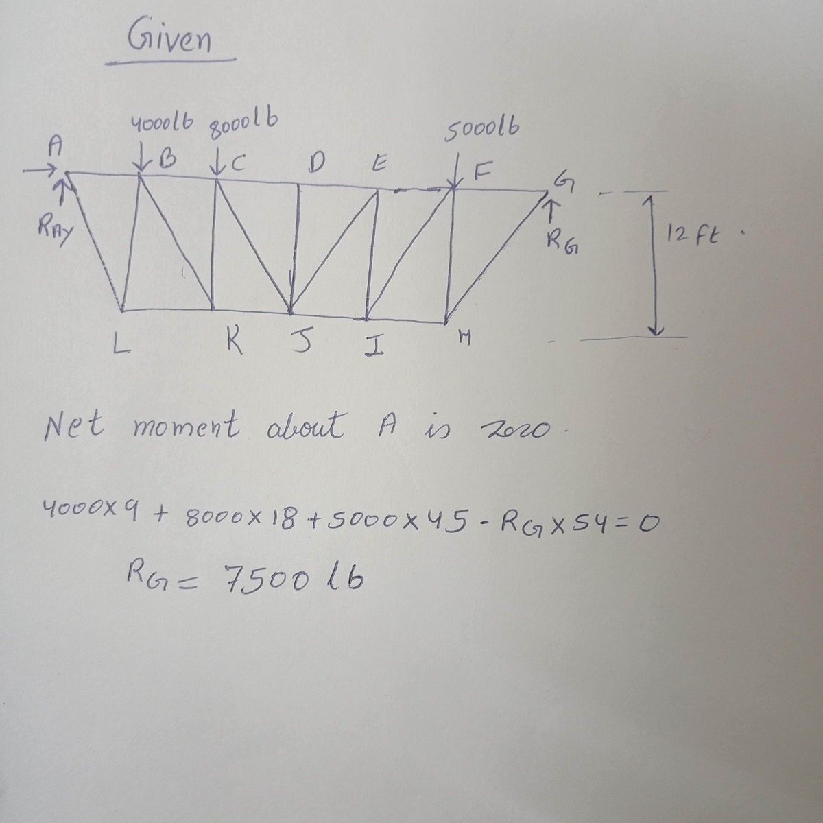
find forces KJ, CD, CJ, and DJ

Transcribed Image Text:The image depicts a truss bridge with labeled points and loads applied at specific locations. The bridge is structured using interconnected members forming triangular shapes, which is a common design for truss systems to distribute weight efficiently.
### Description of the Truss Structure:
- **Points and Members:**
- The truss spans from point A on the left to point G on the right.
- The horizontal members AB, BC, CD, DE, EF, and FG are on the top.
- The bottom members are designated as AL, LK, KJ, JI, IH, and HG.
- Vertical and diagonal members, like BL, CL, CK, DH, EJ, FI, and others, connect the top and bottom components, creating triangular formations.
- **Loads Applied:**
- A load of 4000 lb is applied at point B.
- A load of 8000 lb is at point C.
- A load of 5000 lb is at point F.
- **Dimensions:**
- Each segment of the bridge spans 9 feet horizontally (e.g., between A and L, L and K, etc.).
- The total horizontal length of the truss is composed of six equal sections, each 9 feet, totaling 54 feet.
- The truss has a vertical height of 12 feet between the top chords (points like B, C, and F) and the bottom at point H.
### Truss Design Explanation:
The truss uses a common design seen in engineering to efficiently distribute the loads applied to it. The triangular formations help in transferring the forces through both tension and compression, enhancing the structure's stability and strength.
This kind of truss system is widely utilized in bridges, roofs, and various architectural structures due to its efficiency in handling large spans and significant loads while minimizing material usage.
Expert Solution
Given data

Step by step
Solved in 2 steps with 2 images

Knowledge Booster
Learn more about
Need a deep-dive on the concept behind this application? Look no further. Learn more about this topic, mechanical-engineering and related others by exploring similar questions and additional content below.Recommended textbooks for you

Elements Of Electromagnetics
Mechanical Engineering
ISBN:
9780190698614
Author:
Sadiku, Matthew N. O.
Publisher:
Oxford University Press

Mechanics of Materials (10th Edition)
Mechanical Engineering
ISBN:
9780134319650
Author:
Russell C. Hibbeler
Publisher:
PEARSON

Thermodynamics: An Engineering Approach
Mechanical Engineering
ISBN:
9781259822674
Author:
Yunus A. Cengel Dr., Michael A. Boles
Publisher:
McGraw-Hill Education

Elements Of Electromagnetics
Mechanical Engineering
ISBN:
9780190698614
Author:
Sadiku, Matthew N. O.
Publisher:
Oxford University Press

Mechanics of Materials (10th Edition)
Mechanical Engineering
ISBN:
9780134319650
Author:
Russell C. Hibbeler
Publisher:
PEARSON

Thermodynamics: An Engineering Approach
Mechanical Engineering
ISBN:
9781259822674
Author:
Yunus A. Cengel Dr., Michael A. Boles
Publisher:
McGraw-Hill Education

Control Systems Engineering
Mechanical Engineering
ISBN:
9781118170519
Author:
Norman S. Nise
Publisher:
WILEY

Mechanics of Materials (MindTap Course List)
Mechanical Engineering
ISBN:
9781337093347
Author:
Barry J. Goodno, James M. Gere
Publisher:
Cengage Learning

Engineering Mechanics: Statics
Mechanical Engineering
ISBN:
9781118807330
Author:
James L. Meriam, L. G. Kraige, J. N. Bolton
Publisher:
WILEY